84
5.12.6 User-defined output signal
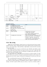
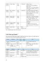
User can define 2 outputs. The defined method is SOx output when A>B or A<B. A is 9 activating
conditions, B is user-defined comparison value.
User-defined output 1:
User-defined output 2:
P5-10
The trigger condition of user-defined output 1
Default trigger
condition
Trigger
condition
setting
Unit
Suitable mode Change
effective
0
See below
table: optional
trigger
condition
Related
to
trigger
condition
All the modes
servo
OFF
At once
P5-11
The comparison value for the trigger condition of user-defined output 1
Unit
Default
setting
Range
Suitable mode Change
Effective
Related to trigger
condition
0
-32768~32767
All the modes
Servo
OFF
At once
P5-12
When P5-10≥P5-11 or P5-10<P5-11, SOx output
Setting
value
Function
Default
value
Suitable
mode
Change
Effective
0
P5-10≥P5-11, SOx output
0
All the
modes
Servo
OFF
At once
1
P5-10
<
P5-11, SOx output
2
P5-10 absolute value ≥P5-11, SOx
output
3
P5-10 absolute value ≤P5-11, SOx
output
P5-13
User-defined output 1 hysteresis loop
Unit
Default
setting
Range
Suitable mode Change
Effective
Related to trigger
condition
0
0~65535
All the modes
Servo
OFF
At once
P5-52
Output terminal setting of user-defined output 1
Signal name
Default
setting
Meaning
Change
User-defined output
1
n.0000
Default setting
is
not
distribute
to
the
output
terminal
Range 0000-0014, distribute to the
output terminal through P5-52.
P5-14
The trigger condition of user-defined output 2
Default trigger
condition
Trigger
condition
setting
Unit
Suitable
mode
Change
Effecti
ve
0
See
below
table:
optional trigger
condition
Related
to
trigger
condition
All the modes
Servo
OFF
At
once
P5-15
The comparison value for the trigger condition of user-defined output 2
Unit
Default setting
Range
Suitable
mode
Change
Effecti
ve
Related
to
trigger
0
-9999~9999
All the modes
Servo
OFF
At
once


