background image

Installing the Printer

Chapter 1: Getting Started

1-19

7

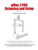
Remove the Toner Cartridge from its package 

and pull out the protective paper sheet from 

the drum shutter.

8

Hold the Toner Cartridge horizontally and 

gently shake it 5 to 6 times to evenly distribute 

the toner inside.

Print quality may be degraded if the 
toner is not evenly distributed. If the 
toner is not freed by shaking the 
cartridge, you may hear a noise when 
powering ON the printer, and the 
cartridge may be damaged.
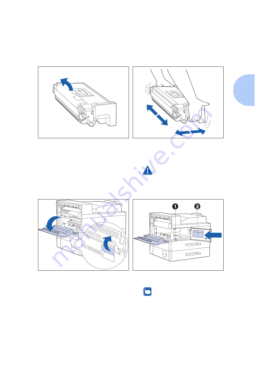
9

Open Door A.

10

Open the front cover.

This reveals the serial number (1) and 
toner install instructions (2).

Summary of Contents for DP N24

Page 1: ...DP N24 N32 and N40 Network Laser Printers System Administrator Guide ...

Page 2: ... WordPerfect Corporation Centronics is a trademark of Centronics Corporation Macintosh and TrueType are trademarks of Apple Computer Incorporated OnPage is a trademark of COMPUTER applications Inc All other product names are trademarks tradenames of their respective owners PCL PCL5e and PCL6 are trademarks of Hewlett Packard Company This printer contains an emulation of the Hewlett Packard PCL com...

Page 3: ...ts 1 6 Special Features 1 8 Connectivity 1 8 Power Saver 1 8 High Resolution Printing 1 8 Edge to Edge Printing 1 9 Automatic Tray Sequencing 1 9 Automatic Language Sensing and Switching 1 9 Automatic Font Macro Saving 1 9 Secure Printing 1 10 Proof Printing 1 10 Printer Generated Reports 1 10 PostScript 1 11 Optional Duplex Printing 1 11 Increased Paper Handling 1 11 ...

Page 4: ...teps 1 18 Maintaining the Printer 1 26 Cleaning the Printer 1 26 Replacing the Toner Cartridge 1 26 Recycling the Toner Cartridge 1 26 Installing the Maintenance Kit 1 27 Moving the Printer 1 28 Transporting the Printer 1 29 Technical Support 1 29 Before Calling for Service 1 29 Accessing Olivetti Via the Internet 1 29 Chapter 2 Paper Handling 2 1 Selecting Paper 2 2 Storing Paper 2 4 Loading Pape...

Page 5: ...ilbox Collator 2 24 Duplex Two Sided Printing 2 25 Print Orientation and Control Panel Settings 2 26 Chapter 3 Using the Control Panel 3 1 Control Panel Features 3 2 The Display 3 3 The Indicator Lights 3 3 The Keys 3 5 Navigating the Menu System 3 9 Menu Indicators 3 10 Control Panel Locks 3 10 Setting a Menu Option 3 11 Main Menu 3 13 Job Menu 3 14 Password Menu 3 16 Tray Menu 3 19 PCL Menu 3 26...

Page 6: ...tions 5 2 Disk Initialization 5 2 Downloading Fonts and Macros 5 3 FSDOWNLOAD Command 5 4 FSDELETE Command 5 7 Using the Hard Disk Drive for Secure and Proof Jobs 5 8 Creating Secure Jobs 5 8 Creating Proof Job 5 10 Printing or Deleting Secure or Proof Jobs 5 11 Chapter 6 Troubleshooting 6 1 Printer Operation Problems 6 2 Control Panel Messages 6 5 Diagnostic LED Flash Sequences 6 24 Paper Jams 6 ...

Page 7: ...B 11 Replacing the Fuser Cartridge and BTR B 12 Replacing the Feedrolls B 17 Resetting the Counter B 22 Cleaning the Printer B 23 Exterior Cleaning B 23 Interior Cleaning B 24 Appendix C Installing and Removing Printer Options C 1 Precautions C 3 2 500 Sheet Feeder C 4 Installing C 4 Removing C 8 Duplex Module C 11 Installing C 11 Removing C 16 10 bin Mailbox Collator C 20 Installing Console Confi...

Page 8: ... D 2 Printing a PCL Font List D 3 PostScript Fonts D 4 Printing a PostScript Font List D 5 Appendix E Printer Specifications E 1 Appendix F DP N40 Unique Printer Commands F 1 Overview F 2 Paper Size Selection F 3 Paper Type Selection F 4 Input Tray Selection F 5 Output Selection F 6 PJL Commands F 7 Appendix G Environmental Specifications G 1 Acoustic Noise Figures G 2 FCC Compliance Statement for...

Page 9: ...r 1 8 High Resolution Printing 1 8 Edge to Edge Printing 1 9 Automatic Tray Sequencing 1 9 Automatic Language Sensing and Switching 1 9 Automatic Font Macro Saving 1 9 Secure Printing 1 10 Proof Printing 1 10 Printer Generated Reports 1 10 PostScript 1 11 Optional Duplex Printing 1 11 Increased Paper Handling 1 11 Multiple Output Options 1 11 Memory Expansion 1 11 Flash Memory SIMMs 1 12 ...

Page 10: ... Space Requirements 1 14 Precautions 1 15 Lifting and Carrying the Printer 1 17 Installation Steps 1 18 Maintaining the Printer 1 26 Cleaning the Printer 1 26 Replacing the Toner Cartridge 1 26 Recycling the Toner Cartridge 1 26 Installing the Maintenance Kit 1 27 Moving the Printer 1 28 Transporting the Printer 1 29 Technical Support 1 29 Before Calling for Service 1 29 Accessing Olivetti Via the...

Page 11: ...ferring to these printers And it refers to all features not found on the base printer as options This guide also identifies two different configurations for the DP N40 The tabletop configuration The console configuration sitting on top of the optional 2 500 Sheet Feeder Samples of each configuration are shown later in this chapter however the figures throughout this guide may show either configura...

Page 12: ...cial Features page 1 8 Printer memory issues Memory Considerations page 1 13 Instructions for installing the printer Installing the Printer page 1 14 Tips on taking care of the printer Maintaining the Printer page 1 26 Tips on transporting the printer Transporting the Printer page 1 29 Contacting Olivetti for technical support Technical Support page 1 29 Paper specifications loading paper and dupl...

Page 13: ...ns Appendix A DP N40 Ordering Information Replacing consumables and cleaning the printer Appendix B Maintaining the Printer Installing and removing printer options Appendix C Installing and Removing Printer Options List of fonts resident on the printer Appendix D Printer Resident Fonts Printer Specifications Appendix E Printer Specifications DP N40 printer command differences for PCL and PostScrip...

Page 14: ...ter components Front View 1 Face up Output Bin 2 Door A 3 50 Sheet Bypass Feeder 4 Door B 5 Face down Output Bin 6 Power switch 7 Control Panel 8 Front cover 9 Paper Tray 1 10 Paper Tray 2 Rear View 1 Power receptacle 2 Hand grips 3 Controller Board with host network interface ports 4 Connectors for optional 2 500 Sheet Feeder 10 bin Mailbox Collator Finisher and Duplex Module ...

Page 15: ...ith options Front View 1 10 bin Mailbox Collator 2 Face up Output Bin 3 Duplex Module 4 100 Envelope Feeder 5 2 500 Sheet Feeder with Paper Trays 3 4 and 5 Figure 1 3 Customer replaceable components Front View Covers Open 1 Fuser 2 Toner Cartridge 3 Bias Transfer Roll BTR 4 Feedrolls ...

Page 16: ...l interface enables the on board 10 Mbit Ethernet functionality again Power Saver After 60 minutes of inactivity the printer automatically turns off internal components to reduce the amount of electricity used The printer automatically turns those parts back on when it receives a print job Using the printer s Control Panel menu system you can send the printer into Power Saver mode after your choic...

Page 17: ...end your printing capacity For more information on tray switching see the section Automatic Tray Switching page 2 16 in Chapter 2 Paper Handling Automatic Language Sensing and Switching The printer can process both PCL and PostScript jobs When the printer s Language Sensing option is on the DP N40 samples the incoming data stream to determine which language the print job requires The DP N40 then s...

Page 18: ...sword Menu via the Printer Control Panel Proof printing jobs are defined and enabled either via the DP N40 printer drivers or via a sequence of PJL commands see Creating Proof Job page 5 10 for an example This feature requires the Hard Disk Drive option Printer Generated Reports Using the printer s Control Panel you can print seven separate reports The Demo Page provides a sample of the printer s ...

Page 19: ... a capacity of 100 envelopes See Appendix A DP N40 Ordering Information to order the 2 500 Sheet Feeder and 100 Envelope Feeder Multiple Output Options The 200 Sheet Face up Bin and the 500 Sheet Face down Bin with offset capability come standard on the DP N40 The Face up Bin holds up to 200 sheets of Letter A4 paper The Face down Bin with offset capability holds up to 500 sheets of paper and can ...

Page 20: ...sheets per bin There is stapling capability for all three bins Stapled output is delivered face down The stapler can staple sets of up to 50 sheets It has three stapling positions Front for portrait Back for landscape and Dual for booklet mode The customer replaceable stapling cartridge contains 5 000 staples The finisher documentation is provided as a separate document on your CD Intelligent Rast...

Page 21: ...ng specifications 8 MB SIMM 72 pins 70 nanosecond access time No parity 2M x 32 bits 16 MB SIMM 72 pins 70 nanosecond access time No parity 4M x 32 bits 32 MB SIMM 72 pins 70 nanosecond access time No parity 8M x 32 bits Additional memory will provide the following enhanced DP N40 capabilities Additional font cache Additional download space for fonts macros and images Increased throughput for comp...

Page 22: ...e continuing on to the installation steps This section contains important information concerning your safety and the safety of the printer Space Requirements For easy operation maintenance and replacing of consumables you should select a location for the printer that leaves the minimum clearances around the printer as shown in Figure 1 4 for a base configuration and in Figure 1 5 on page 1 15 when...

Page 23: ...ches 100 mm 4 12 inches 305 mm 5 36 inches 915 mm 6 72 inches 1830 mm To avoid fire hazard Do not place the printer in a location with high temperature and humidity poor ventilation or a high level of dust Do not place the printer near heaters or similar objects Never block the printer s ventilation openings Be sure to leave ample space between the ventilation openings and the nearest wall or othe...

Page 24: ...o not bend pull or place heavy objects on the extension cord Never touch the GFI Ground Fault Interrupt or plug with wet hands If you do not use the GFI Olivetti does not guarantee the successful operation of your machine To avoid printer malfunction or damage Position the printer on a horizontal sturdy and stable surface Operate the printer under temperature conditions of 10 to 35 C 50 to 95 F wi...

Page 25: ...rself THE PRINTER SHOULD ALWAYS BE CARRIED BY TWO PEOPLE To carry the printer grasp the bottom corners on the right side as shown in Figure 1 6 not from the front where the control panel is located and back sides On the left side hold both corners of the 50 Sheet Bypass Feeder to avoid injury to fingers when setting the printer down Also when lifting the printer correct posture is important to avo...

Page 26: ...Remove the plastic bag and pieces of tape from the printer 3 Complete the registration card See Step on page 1 19 for the location of the serial number 4 If you are setting up the printer in its console configuration refer to Appendix C Installing and Removing Printer Options for instructions on installing the 2 500 Sheet Feeder then return to this procedure 5 With two people lift up the printer a...

Page 27: ...horizontally and gently shake it 5 to 6 times to evenly distribute the toner inside Print quality may be degraded if the toner is not evenly distributed If the toner is not freed by shaking the cartridge you may hear a noise when powering ON the printer and the cartridge may be damaged 9 Open Door A 10 Open the front cover This reveals the serial number 1 and toner install instructions 2 ...

Page 28: ... in the printer 12 Gently pull the sealing tape straight out in the direction of the arrow If the tape is pulled out at an angle it may break 13 Close Door A and the front cover When closing Door A do not use the latch on the cover Instead follow the instruction label on the cover for the correct location to push the cover closed 14 If you are installing the optional Duplex Module skip to Step on ...

Page 29: ...ere are two sets of screws a longer pair 3 and a shorter pair 4 SAVE ALL OF THESE PARTS Some are used with the Duplex Module 16 Attach the bracket to the printer with the supplied longer screws Tighten by hand 17 Attach the bin to the connecting plate with the supplied shorter screws 18 Hook the bin and connecting plate on the bracket Make sure they are firmly seated ...

Page 30: ...out Paper Tray 1 shown above or Tray 2 until it stops 20 Prepare a stack of paper making sure the tops of the sheets are aligned 21 Gently lift up the width guide and slide it all the way until it stops 22 Press down the gray handle and slide the side guide all the way until it stops ...

Page 31: ...ted mark 24 Adjust the side guide to the paper length 25 Align the edges of the paper stack 26 Adjust the width guide to the paper width To avoid paper jams make sure the guide stopper is locked firmly in the guide hole on the bottom of the tray and that both the side and length guides are set correctly for the size of paper you are using ...

Page 32: ...ches For complete paper size and loading information refer to Chapter 2 Paper Handling 28 Repeat the paper loading steps for the other paper tray s 29 If you have other options to install refer to Appendix C Installing and Removing Printer Options for instructions Otherwise you can proceed to the next step and complete the installation 30 Attach the interface cable from your host computer or netwo...

Page 33: ... not use the GFI power cord Olivetti does not guarantee the successful operation of your machine Go to Step 34 33 Attach the 220V GFI Ground Fault Interrupt and power cord and plug into AC outlet If you do not use the GFI power cord Olivetti does not guarantee the successful operation of your machine 34 Power ON the printer Save all remaining parts as you may need them at some later time ...

Page 34: ...ays power the printer off before cleaning See Appendix B Maintaining the Printer for more details Replacing the Toner Cartridge The Toner Cartridge will print approximately 23 000 impressions of A4 or 8 5 x 11 paper under average operating conditions 5 image area coverage The number of prints per cartridge will decrease if you routinely print dense text and graphics Replace the Toner Cartridge as ...

Page 35: ... that point or sometime in between the occurrence of the two messages install the Maintenance Kit All instructions necessary for replacing the Fuser BTR and feedrolls are contained in the Maintenance Kit All these components are designed to be user installable however a Olivetti Service Representative can be called to install the Maintenance Kit for a fee See Appendix A DP N40 Ordering Information...

Page 36: ... before moving it and be sure to notify all users that it will be offline during the move If in the tabletop configuration be sure to use two people as shown in the section Lifting and Carrying the Printer page 1 17 If in the console configuration unlock the casters to roll the printer To avoid tipping the printer over be sure not to tilt it more than 10 as shown in Figure 1 7 Figure 1 7 Maximum t...

Page 37: ...ackaging 4 Pack the printer with the Toner Cartridge sealed in a plastic bag and GFI power cord in the original printer box Technical Support If you are unable to resolve a printing problem using the instructions in Chapter 6 Troubleshooting contact the dealer from which you bought your printer or contact Olivetti Before Calling for Service Before contacting your dealer or Olivetti please have the...

Page 38: ...Technical Support 1 30 DP N24 N32 and N40 System Administrator Guide ...

Page 39: ...heet Bypass Feeder 2 11 Using the 100 Envelope Feeder 2 15 Automatic Tray Switching 2 16 Tray Sequence Settings 2 17 Paper Handling Exception Conditions 2 18 Tray Sequence Rules 2 20 Tray Sequence Examples 2 21 Paper Size Type Mismatch 2 22 Offsetting Output 2 23 Using the 10 bin Mailbox Collator 2 24 Printing to the Mailbox Collator 2 24 Duplex Two Sided Printing 2 25 Print Orientation and Contro...

Page 40: ... Using sizes other than those listed in Table 2 1 or paper not recommended for laser printers may result in paper jams and print quality problems The following media are unacceptable for use in the DP N40 Excessively thick or thin paper Paper that has already been printed on preprinted letterhead is allowed Wrinkled torn or bent paper Moist or wet paper Curled paper Paper with an electrostatic cha...

Page 41: ...ox Collator A3 297x420 mm A4 210x297 mm A5 148x210 mm A6 105x148 mm Statement 5 5x8 5 140x216 mm Executive7 25x10 5 184x267 mm Letter 8 5x11 216x279 mm Folio 8 5x13 216x330 mm Legal 8 5x14 216x356 mm Ledger 11x17 279x432 mm Envelopes COM 10 4 125x9 5 105x241mm Monarch 3 87x7 5 98x191mm DL 4 33x8 66 110x220 mm C5 6 38x9 01 162x229 mm Transparencies A4 210x297 mm Letter 8 5x11 216x279mm Tray 2 Tray ...

Page 42: ...eets and 2 500 sheets in the printer see page 2 5 Tray 3 500 sheets the top tray in the optional 2 500 Sheet Feeder also see page 2 5 Trays 4 1 000 sheets the lower left tray and 5 1 000 sheets the lower right tray in the optional 2 500 Sheet Feeder see page 2 9 The 50 Sheet Bypass Feeder in the printer see page 2 11 The optional 100 Envelope Feeder see page 2 15 Do not attempt to load paper durin...

Page 43: ...on Selecting Paper page 2 2 for acceptable paper sizes and weights 1 Pull out the tray Tray 1 is shown above until it stops 2 Prepare a stack of paper making sure the tops of the sheets are aligned 3 Gently lift up the width guide and slide it all the way until it stops If you are replacing paper of the same size skip to Step 5 on page 2 6 4 Press down the gray handle and slide the side guide all ...

Page 44: ... 2 8 for orientation Do not stack paper above the indicated mark 6 Adjust the side guide to the paper length 7 Align the edges of the paper stack 8 Adjust the width guide to the paper width Make sure the guide is locked firmly in the guide hole on the bottom of the tray and that both the side and width guides are set correctly for the size of paper you are using ...

Page 45: ...aper size slot on the front of the tray 10 Push the tray all the way back into the printer until it latches Figure 2 1 Trays 1 2 3 paper orientation long edge feed Top View 1 Duplex printing 2 Simplex printing Load the following paper sizes with the long edge on the left leading into the printer Letter Statement Executive A4 A5 ...

Page 46: ...feed Top View 1 Duplex printing 2 Simplex printing Load the following paper sizes with the short edge on the left leading into the printer Legal Folio Ledger A3 The paper in this illustration looks like letter or A4 size paper but it is not The graphic is only a generic representation of the paper sizes listed above ...

Page 47: ... and Executive size only The following procedure uses Tray 4 as an example but can be used for Tray 5 as well 1 Pull out the tray until it stops 2 Prepare a stack of paper making sure the tops of the sheets are aligned 3 Place paper in the tray against the left side refer to Figure 2 3 on page 2 10 for orientation Slide back the stop Do not stack paper above the indicated mark 4 Push the tray back...

Page 48: ... Top View Tray 4 1 Duplex printing 2 Simplex printing Load the following sizes with the long edge on the left leading into the printer Letter Executive A4 Top View Tray 5 1 Duplex printing 2 Simplex printing Load the following sizes with the long edge on the left leading into the printer Letter Executive A4 ...

Page 49: ... weights 1 If necessary pull out the extension tray to fit the length of paper to be used 2 Place the paper along the right side of the Bypass Feeder refer to Figure 2 4 on page 2 12 and Figure 2 5 on page 2 13 for paper orientation and Figure 2 6 on page 2 14 for envelope orientation 3 Push the paper guide to slightly touch the paper stack to ensure contact with the paper sensor 4 Push the paper ...

Page 50: ...ay and push back the extension tray if necessary as paper will be fed from the Bypass Feeder if it is selected in the tray sequence Figure 2 4 50 Sheet Bypass Feeder paper orientation long edge feed Top View 1 Simplex printing 2 Duplex printing Load the following paper sizes with the long edge leading into the printer Letter Statement Executive A4 A5 ...

Page 51: ...r Handling 2 13 Figure 2 5 50 Sheet Bypass Feeder paper orientation short edge feed Top View 1 Simplex printing 2 Duplex printing Load the following paper sizes with the short edge leading into the printer Legal Folio Ledger A3 A6 ...

Page 52: ...der envelope orientation1 Top View 1 Envelope 2 DL Envelope 3 C5 Envelope 1 Some PostScript applications require that the envelopes be loaded with the return address corner on the right side of the stack and leading as the envelopes go into the printer Test your application for proper orientation ...

Page 53: ... 1 Prepare a stack of envelopes making sure all flaps are closed and the envelopes are not stuck together 2 Lift the envelope stopper and insert the stack with the flap side up and the long edges leading into the printer 3 Slide the side guide so that it lightly touches the edges of the envelope stack To avoid paper jams do not stack envelopes above the paper limit mark and do not attempt to add e...

Page 54: ...es not match the paper loaded in the current paper tray the printer automatically searches the next tray in the sequence for a paper size and type that matches Loading paper in one tray while printing from another tray filling an empty tray while printing Tray switching is made possible via the Tray Sequence item in the Control Panel s Tray Menu It enables grouping of Trays 1 and 2 in the printer ...

Page 55: ... settings available with base configuration printer The default settings are either MBF 1 2 when the 50 Sheet Bypass Feeder is installed or 1 2 when the optional 100 Envelope Feeder is installed MBF 4 5 MBF 4 5 1 MBF 4 5 1 2 MBF 4 5 1 2 3 1 2 3 4 1 4 1 2 4 1 2 3 4 5 1 4 5 1 2 4 5 1 2 3 Additional Tray Sequence settings available when the 2 500 Sheet Feeder is installed The default settings are eit...

Page 56: ...ed Not specified Not specified Default size Default type Not specified Not specified Specified not manual feed Default size Type configured in specified tray Not specified Not specified Specified manual feed Manual feed request Default size Not specified Specified Not specified Specified size Default type Not specified Specified Specified not manual feed Specified size Type configured in specified...

Page 57: ... the fourth column of Table 2 3 does not list a paper source to use even though the paper source may be specified If the paper source is specified and the other parameters can be satisfied by that paper source then the specified source is used If the specified source cannot satisfy the request but another source can satisfy the paper size and type requested then that alternate source is used with ...

Page 58: ...en it is used If the tray does not contain the correct paper e g it contains other paper or is empty the other trays in the sequence are searched If any of these trays contains the correct paper then it is used If any of these trays are set to the correct paper size and type but all of the trays in the sequence are empty then the printer will prompt you to load paper into the specified tray If no ...

Page 59: ...uested paper in at least one tray in the sequence The Tray Sequence is set to 1 2 3 A Tray 2 paper source is requested All trays meet the size type requirement The printer feeds paper from Tray 2 because it meets the size and type requested When Tray 2 becomes empty the printer feeds from Trays 1 and 3 The Tray Sequence is set to 1 2 Trays 1 and 2 are set to Letter paper but both trays are empty L...

Page 60: ...ize and type in the appropriate tray After the tray is loaded printing continues If the request is for paper that is not configured in the printer you are prompted to load the requested paper in the first tray of the Tray Sequence setting If you do not want to load paper in the first tray of the Tray Sequence setting two options are available One of the trays may be loaded with the requested size ...

Page 61: ...the PostScript job If the banner sheet is directed to the Face up Bin no offset capability and the PostScript job is directed to the Face down Bin offset does not occur between the banner sheet and the PostScript job If however the next job is directed to the Face down Bin offset will occur between the PostScript job and the next job The offset function occurs between successive jobs directed to t...

Page 62: ... See Appendix C Installing and Removing Printer Options for installation instructions The Mailbox Collator offers the following capabilities Directing output to a specific mailbox bin Sorting by sending individual copies up to 10 of a multiple set job to separate mailbox bins Printing multiple collated sets 2 to 10 sets of a job Printing to the Mailbox Collator Using a DP N40 printer driver select...

Page 63: ...abel paper for duplex jobs Refer to Figure 2 1 on page 2 7 and Figure 2 4 on page 2 12 for the proper orientation of drilled paper and letterhead when printing duplex Table 2 5 Paper sizes that can be used with the Duplex Module Paper Size Weight A3 297 x 420 mm 17 lb 64 g m2 to 24 lb 90 g m2 A4 210 x 297 mm 17 lb 64 g m2 to 24 lb 90 g m2 A5 148 x 210 mm 17 lb 64 g m2 to 24 lb 90 g m2 Statement 5 ...

Page 64: ...em Menu to the appropriate setting see Figure 2 7 The Duplex settings for both PCL and PostScript are as follows Duplex Off Duplex Short Edge or Duplex Long Edge Figure 2 7 Duplex binding orientation and Control Panel menu settings Portrait Orientation Set Duplex to Long Edge Portrait Orientation Set Duplex to Short Edge Landscape Orientation Set Duplex to Long Edge Landscape Orientation Set Duple...

Page 65: ...Keys 3 5 Navigating the Menu System 3 9 Menu Indicators 3 10 Control Panel Locks 3 10 Setting a Menu Option 3 11 Main Menu 3 13 Job Menu 3 14 Password Menu 3 16 Tray Menu 3 19 PCL Menu 3 26 PostScript Menu 3 31 System Menu 3 33 Parallel Menu 3 42 Serial Menu 3 45 Ethernet Menu 3 48 Token Ring Menu 3 61 Novell Menu 3 75 Test Menu 3 82 Reset Menu 3 87 ...

Page 66: ...plays information about the status of the printer or the job in process 2 It provides the means for changing printer settings and printer defaults to control how the DP N40 operates As shown in Figure 3 1 your printer s Control Panel will have icons Figure 3 1 DP N40 Control Panel 1 Indicator lights 2 2 line by 16 character display 3 Control keys 8 ...

Page 67: ...y will also show Processing when processing data Waiting when waiting for more data 2 It presents a hierarchy of menu options and settings to configure and control the printer For example when you press Menu Up or Menu Down you will see the following two line message on the display Menus Item Menu such as Job Menu See the section Menu Indicators page 3 10 for more information on indicators See the...

Page 68: ...print partial pages and consequently the Form Feed light is not turned On The Form Feed light is turned Off when either an actual Form Feed character is received or the Form Feed function is invoked by pressing Enter on the Job Menu when the Form Feed item is displayed Fault Amber The Error light is On whenever operator intervention is required in order to allow printing to continue Data Green Whe...

Page 69: ...or an open cover Pressing On Line under the following conditions results in the actions stated If the printer is online and in the Menu system the printer remains online and an exit from the Menu system takes place If the printer is offline and not in the Menu system the printer switches to online as long as operator intervention is not required The printer remains offline if operator intervention...

Page 70: ...splays it may preempt menu navigation Menu scrolling is available without going offline Menu scrolling wraps if the displayed menu is the last menu If not in the Menu system pressing this key enters the Menu system and displays the last menu If in the Password Menu and the display indicates Enter Password pressing this key causes a password digit 5 to be entered Item Up When in the Menu system scr...

Page 71: ...vigation Scrolling wraps if the displayed item is the first item Press Value Up for more than one second to scroll continuously through numeric values for items that have numeric values such as Font Number or Pitch If no value for the current item is displayed i e Item key was pressed but Value key not yet pressed for this item pressing Value Up displays the default value for the current item When...

Page 72: ...ondition does not exist this key is ignored If a paper mismatch condition exists pressing this key scrolls down through the alternate paper that may by used instead of the requested paper If in the Password Menu and the display indicates Enter Password pressing this key causes a password digit 7 to be entered Enter When in the Menu system sets values and invokes actions or functions If the current...

Page 73: ...nu requires the Token Ring Card Novell Menu Test Menu Press Menu Up or Menu Down to access the Main Menu Each of the submenus may have other submenus settings actions or functions Reset Menu and its functions Language Menu Factory Defaults Menu Reset Network Defaults Menu Reset Demo Mode Delete Jobs Init Disk requires the Hard Disk option The Reset Menu is included in the menu list by simultaneous...

Page 74: ...et Menu If you do not want users to have access to the Reset Menu power OFF and power ON the printer Table 3 3 Indicators found in the Control Panel Menu systems Indicator Purpose Example This indicator only appears after options which take a specific setting it indicates that a value or setting follows the option The example at the right tells you that Language is an option that takes a specific ...

Page 75: ...submenu all submenus except the Password Menu You will see Menu Name Item Name Where Item Name is the current item displayed For the Job Test and Reset with the exception of the Language option Menus the bottom line of the display indicates the action to be taken e g Config Sheet or PCL Font List 3 Press Value Up or Value Down to select the appropriate value for this item You will see Item Name Cu...

Page 76: ...a value the menu will display Menu Name Item Name You may either continue to work in the Menu system by repeating the steps above or exit and return to normal operation by pressing On Line If you press On Line at any time prior to pressing Enter the new value will not be saved and the Menu system is exited The printer automatically exits the Menu system after 60 seconds of inactivity i e no key ha...

Page 77: ...e Job Menu page 3 14 Password Menu1 See Password Menu page 3 16 Tray Menu See Tray Menu page 3 19 PCL Menu See PCL Menu page 3 26 PostScript Menu See PostScript Menu page 3 31 System Menu See System Menu page 3 33 Parallel Menu See Parallel Menu page 3 42 Serial Menu See Serial Menu page 3 45 Ethernet Menu See Ethernet Menu page 3 48 Token Ring Menu2 See Token Ring Menu page 3 61 Novell Menu3 See ...

Page 78: ...orm feed on a partially formatted job in PCL The Job Menu hierarchy is shown in Figure 3 2 Tasks performed with Job Menu items are listed in Table 3 5 on page 3 15 Figure 3 2 Job Menu hierarchy Job Menu Cancel Job Password Menu Form Feed Tray Menu PCL Menu PostScript Menu System Menu Parallel Menu Serial Menu Ethernet Menu Token Ring Menu Novell Menu Test Menu Reset Menu ...

Page 79: ...inting 1 Press Menu Up or Menu Down until you see Menus Job Menu 2 Press Item Up or Item Down until you see Job Menu Cancel Job 3 Press Enter You will see Ready Form Feed Force a form feed on a partially formatted job in PCL 1 Press Menu Up or Menu Down until you see Menus Job Menu 2 Press Item Up or Item Down until you see Job Menu Form Feed 3 Press Enter You will see Ready ...

Page 80: ...Enter Password No Jobs Press Menu Tray Menu _xxx PCL Menu All Jobs Print PostScript Menu Delete System Menu Parallel Menu Job n Print Serial Menu Delete Ethernet Menu Token Ring Menu Novell Menu Test Menu Reset Menu Secure or proof job printing requires the use of a four digit password sent with the print job to the printer as described in the section Using the Hard Disk Drive for Secure and Proof...

Page 81: ...nter You will see Ready Job n Print Print one or more jobs out of several sent with a specific password A job with a name assigned to it will replace the Job n with that name 1 Press Menu Up or Menu Down until you see Menus Password Menu 2 Press Item Up or Item Down You will see Enter Password _xxx 3 Enter four digit password using the numbers on the Control Panel keys You will see All Jobs Print ...

Page 82: ...elete one or more jobs out of several sent with a specific password 1 Press Menu Up or Menu Down until you see Menus Password Menu 2 Press Item Up or Item Down You will see Enter Password _xxx 3 Enter four digit password using the numbers on the Control Panel keys You will see All Jobs Print 4 Press Item Up or Item Down until you see Job n Print 5 Press Value Up or Value Down until you see Job n D...

Page 83: ... Tray Menu The Tray Menu allows you to access tray settings that are common to all system languages PCL and PostScript The Tray Menu hierarchy is shown in Figure 3 4 on page 3 20 Tasks performed with the Tray Menu are listed in Table 3 7 on page 3 21 ...

Page 84: ...35 1 Envelope Size and MBF Size are mutually exclusive because the Envelope Feeder replaces the Multi Bypass Feeder 2 Defaults to Com10 if the Defaults item in the System Menu is set to USA and to DL if the Defaults item is set to Europe 3 The factory defaults for MBF size and Envelope size are a function of the default setting in the System Menu 4 Defaults to Letter if the Defaults item in the Sy...

Page 85: ...e 4 Press Enter You will see Tray Menu Envelope Size 5 Press On Line You will see Ready MBF Size Set the paper size that is loaded in the 50 Sheet Bypass Feeder MBF The available values are Statmt 5 5x8 5 A5 148x210 Exec 7 25x10 5 A4 210x297 Letter 8 5x11 A3 297x420 Legal 8 5x14 Com10 4 125x9 5 Folio 8 5x13 C5 162x229 Ledger 11x17 DL 110x220 A6 105x148 Monarc 3 87x7 5 Letter is the U S default A4 ...

Page 86: ...alue 4 Press Enter You will see Tray Menu MBF Type 5 Press On Line You will see Ready Tray 1 Type Set the type of paper that is loaded in Tray 1 The available values are Plain Color Preprinted Cardstock Letterhead User Type 1 if loaded Transparency User Type 2 if loaded Prepunched User Type 3 if loaded Labels User Type 4 if loaded Bond User Type 5 if loaded Recycled 1 Press Menu Up or Menu Down un...

Page 87: ... Type 5 Press On Line You will see Ready Tray 3 Type Set the type of paper that is loaded in Tray 3 The available values are Plain Color Preprinted Cardstock Letterhead User Type 1 if loaded Transparency User Type 2 if loaded Prepunched User Type 3 if loaded Labels User Type 4 if loaded Bond User Type 5 if loaded Recycled Available only when the optional 2 500 Sheet Feeder is installed 1 Press Men...

Page 88: ...ess Enter You will see Tray Menu Tray 4 Type 5 Press On Line You will see Ready Tray 5 Type Set the type of paper that is loaded in Tray 5 The available values are Plain Color Preprinted Cardstock Letterhead User Type 1 if loaded Transparency User Type 2 if loaded Prepunched User Type 3 if loaded Labels User Type 4 if loaded Bond User Type 5 if loaded Recycled Available only when the optional 2 50...

Page 89: ...500 Sheet Feeder The first tray of a sequence is used until it runs out of paper at which time the next tray in the sequence is used if it has the correct paper size and type See the section Automatic Tray Switching page 2 16 for rules and examples of usage 1 Press Menu Up or Menu Down until you see Menus Tray Menu 2 Press Item Up or Item Down until you see Tray Menu Tray Sequence 3 Press Value Up...

Page 90: ...Menu Point Size1 4 00 999 75 by 25 12 00 System Menu Parallel Menu Form Length 005 128 60 for U S 64 for Europe Serial Menu Ethernet Menu Symbol Set Desktop ISO 69 PS Text Token Ring Menu ISO L1 Legal Roman 8 Novell Menu ISO L2 Math 8 Vn Int l Test Menu ISO L5 Ms Publ Vn Math ISO 4 PC 8 Vn US ISO 6 PC 8 DN Win 3 0 ISO 11 PC 8 Tk Win L1 ISO 15 PC 850 Win L2 ISO 17 PC 852 Win L5 ISO 21 Pi Font ISO L...

Page 91: ...Menu Down until you see Menus PCL Menu 2 Press Item Up or Item Down until you see PCL Menu Font Number 3 Press Value Up or Value Down until you see Font Number New Value 4 Press Enter You will see PCL Menu Font Number 5 Press On Line You will see Ready Pitch Set the pitch of the PCL default font when the PCL default font is a scalable fixed pitch font The available values are 44 99 99 10 00 The pi...

Page 92: ... or Value Down is pressed Holding down Value Up or Value Down causes continuous scrolling through the point sizes 1 Press Menu Up or Menu Down until you see Menus PCL Menu 2 Press Item Up or Item Down until you see PCL Menu Point Size 3 Press Value Up or Value Down until you see Point Size New Value 4 Press Enter You will see PCL Menu Point Size 5 Press On Line You will see Ready Table 3 8 PCL Men...

Page 93: ...ch 6 The Form Length value changes incrementally by 1 each time either Value Up or Value Down is pressed Holding down Value Up or Value Down causes continuous scrolling through the Form Length values The value of this setting after performing a Reset Menus depends on the value of the Defaults setting 1 Press Menu Up or Menu Down until you see Menus PCL Menu 2 Press Item Up or Item Down until you s...

Page 94: ...Down until you see Menus PCL Menu 2 Press Item Up or Item Down until you see PCL Menu Symbol Set 3 Press Value Up or Value Down until you see Symbol Set New Value 4 Press Enter You will see PCL Menu Symbol Set 5 Press On Line You will see Ready Line Terminat Cause a Carriage Return to be added after every Line Feed appearing in the PCL text The available values are Off On This setting enables the ...

Page 95: ...nd information and instructions to the printer The PostScript Menu hierarchy is shown in Figure 3 6 Tasks performed with the PostScript Menu are listed in Table 3 9 on page 3 32 Figure 3 6 PostScript Menu hierarchy with factory settings Job Menu Password Menu Tray Menu PCL Menu PostScript Menu Print Errors Off System Menu On Parallel Menu Serial Menu Binary PS Off Ethernet Menu On Token Ring Menu ...

Page 96: ... will see PostScript Menu Print Errors 5 Press On Line You will see Ready Binary PS Enable or disable the binary mode of PostScript The available values are Off On The parameter applies to all protocols and interfaces except the following Parallel Serial EtherTalk TokenTalk EtherTalk and TokenTalk are always set to Binary mode Parallel and Serial cannot be set to Binary mode 1 Press Menu Up or Men...

Page 97: ...A3 297x420 C5 162x229 Tray Menu Letter 8 5x11 2 A4 210x297 2 DL 110x220 PCL Menu Legal 8 5x14 A5 148x210 Monarc 3 87x7 5 PostScript Menu Folio 8 5x13 A6 105x148 System Menu Parallel Menu Paper Type Plain Labels User type 1 Serial Menu Preprinted Bond User type 2 Ethernet Menu Letterhead Recycled User type 3 Token Ring Menu Transparency Color User type 4 Novell Menu Prepunched Cardstock User type 5...

Page 98: ...s USA Europe 1 Defaults to Letter when the Defaults item is set to USA Defaults to A4 when the Defaults item is set to Europe 2 The factory default for paper size depends on the default settings in the System Menu 3 Appears only when the Duplex Module is installed 4 Appears only when the 10 bin Mailbox Collator or Finisher is installed 5 Appears only when the 10 bin Mailbox collator is installed F...

Page 99: ...Paper Size 3 Press Value Up or Value Down until you see Paper Size New Value 4 Press Enter You will see System Menu Paper Size 5 Press On Line You will see Ready Paper Type Set the default paper type used in PostScript and PCL The available values are Plain Color Preprinted Cardstock Letterhead User Type 1 if loaded Transparency User Type 2 if loaded Prepunched User Type 3 if loaded Labels User Ty...

Page 100: ...Menus System Menu 2 Press Item Up or Item Down until you see System Menu Page Policy 3 Press Value Up or Value Down until you see Page Policy New Value 4 Press Enter You will see System Menu Page Policy 5 Press On Line You will see Ready Page Timeout Direct the printer how long to wait before taking the action defined by the setting of the Page Policy item The available values are 300 180 120 60 3...

Page 101: ...Press Value Up or Value Down until you see Copies New Value 4 Press Enter You will see System Menu Copies 5 Press On Line You will see Ready Orientation Set the default orientation used in PCL and PostScript The available values are Portrait Landscape 1 Press Menu Up or Menu Down until you see Menus System Menu 2 Press Item Up or Item Down until you see System Menu Orientation 3 Press Value Up or ...

Page 102: ...Down until you see Duplex New Value 4 Press Enter You will see System Menu Duplex 5 Press On Line You will see Ready Draft Mode Enable or disable the reduced toner mode for draft printing The available values are Off On When set to On the printer automatically reduces the amount of toner by two thirds and prints a draft quality output 1 Press Menu Up or Menu Down until you see Menus System Menu 2 ...

Page 103: ...4 Press Enter You will see System Menu Edge to Edge 5 Press On Line You will see Ready Output Timeout Determine how many seconds the system will wait after a bin is filled before directing output to the Face down Tray The available values are Off 0 30 60 120 180 300 1 Press Menu Up or Menu Down until you see Menus System Menu 2 Press Item Up or Item Down until you see System Menu Output Timeout 3 ...

Page 104: ... Dest Set the default paper output destination The available values are Face Down Bin Face Up Bin Mailbox 1 Mailbox 10 Sorter Mailbox bins 1 through 10 are only available when the optional 10 bin Mailbox Collator is installed For more information on printing to the Mailbox Collator refer to the section Using the 10 bin Mailbox Collator page 2 24 1 Press Menu Up or Menu Down until you see Menus Sys...

Page 105: ...When set to Europe the default Paper Size value is set to A4 the default MBF Size is set to A4 and the default Envelope Size is set to DL When set to USA the default Paper Size value is set to Letter the default MBF Size is set to Letter and the default Envelope Size is set to Com10 The default Form Length value in the PCL Menu is adjusted to match the Paper Size The Defaults setting is not change...

Page 106: ...3 8 Tasks performed with the Parallel Menu are listed in Table 3 11 on page 3 43 Figure 3 8 Parallel Menu hierarchy with factory settings Job Menu Port Enable On Password Menu Off Tray Menu PCL Menu Port Timeout 5 300 30 PostScript Menu System Menu Parallel PDL Auto Parallel Menu PCL Serial Menu PostScript Ethernet Menu Token Ring Menu Novell Menu On Test Menu Bidirectional Off Reset Menu ...

Page 107: ... print job and poll the next port in the polling sequence The available values are 5 300 seconds 30 This item also causes an implicit job end such as Control D in PostScript or ESC E in PCL and invokes the emulation functions associated with this action e g formfeed reset etc The time changes incrementally by 1 second each time either Value Up or Value Down is pressed Holding down Value Up or Valu...

Page 108: ...will see Parallel Menu Parallel PDL 5 Press On Line You will see Ready Bidirectional Enable or disable bidirectional communications through the parallel port The available values are On Off 1 Press Menu Up or Menu Down until you see Menus Parallel Menu 2 Press Item Up or Item Down until you see Parallel Menu Bidirectional 3 Press Value Up or Value Down until you see Bidirectional New Value 4 Press...

Page 109: ...h factory settings1 Job Menu Port Enable On Password Menu Off Tray Menu PCL Menu Port Timeout 5 300 30 PostScript Menu System Menu Serial PDL Auto Parallel Menu PCL Serial Menu PostScript Ethernet Menu Token Ring Menu Handshake XON Novell Menu Robust XON Test Menu Hardware Reset Menu Baud Rate 115200 9600 57600 4800 38400 2400 28800 1200 19200 600 1 For these changes to take place you must either ...

Page 110: ...ete print job and poll the next port in the polling sequence The available values are 5 300 seconds 30 This item also causes an implicit job end such as Control D in PostScript or ESC E in PCL and invokes the emulation functions associated with this action e g formfeed reset etc The time changes incrementally by 1 second each time either Value Up or Value Down is pressed Holding down Value Up or V...

Page 111: ...nu Down until you see Menus Serial Menu 2 Press Item Up or Item Down until you see Serial Menu Handshake 3 Press Value Up or Value Down until you see Handshake New Value 4 Press Enter You will see Serial Menu Handshake 5 Press On Line You will see Ready Baud Rate Set the baud rate for the serial port The available values are 115200 9600 57600 4800 38400 2400 28800 1200 19200 600 1 Press Menu Up or...

Page 112: ...d in Table 3 13 on page 3 50 Figure 3 10 Ethernet Menu hierarchy with factory settings Job Menu Novell Enable On Password Menu Off Tray Menu PCL Menu LPR Enable On PostScript Menu Off System Menu Parallel Menu LPR Banner On Serial Menu Off Ethernet Menu Token Ring Menu LPR PDL Auto PostScript Novell Menu PCL Test Menu Reset Menu DLC LLC Enable On Off DLC PDL Auto PostScript PCL NetBEUI Enable On O...

Page 113: ... Off IP Address Res Control Panel DHCP BOOTP RARP IP Address xxx xxx xxx xxx Subnet Mask xxx xxx xxx xxx Default Gateway xxx xxx xxx xxx Port Timeout 5 300 30 Speed1 Auto 100 Mbit 10 Mbit 1 This option appears only if the 10 100 Ethernet Network Interface Card NIC is installed Figure 3 10 Ethernet Menu hierarchy with factory settings continued ...

Page 114: ...ble 3 Press Value Up or Value Down until you see Novell Enable New Value 4 Press Enter You will see Ethernet Menu Novell Enable 5 Press On Line You will see Ready LPR Enable Enable or disable the Ethernet LPR protocol The available values are On Off 1 Press Menu Up or Menu Down until you see Menus Ethernet Menu 2 Press Item Up or Item Down until you see Ethernet Menu LPR Enable 3 Press Value Up or...

Page 115: ...ee Ethernet Menu LPR Banner 5 Press On Line You will see Ready LPR PDL Set the default emulation for the Ethernet LPR protocol The available values are Auto PCL PostScript 1 Press Menu Up or Menu Down until you see Menus Ethernet Menu 2 Press Item Up or Item Down until you see Ethernet Menu LPR PDL 3 Press Value Up or Value Down until you see LPR PDL New Value 4 Press Enter You will see Ethernet M...

Page 116: ...nter You will see Ethernet Menu DLC LLC Enable 5 Press On Line You will see Ready DLC PDL Set the default emulation for the DLC protocol The available values are Auto PCL PostScript 1 Press Menu Up or Menu Down until you see Menus Ethernet Menu 2 Press Item Up or Item Down until you see Ethernet Menu DLC PDL 3 Press Value Up or Value Down until you see DLC PDL New Value 4 Press Enter You will see ...

Page 117: ...e Ethernet Menu NetBEUI Enable 5 Press On Line You will see Ready NetBEUI PDL Set the default emulation for the NetBEUI protocol The available values are Auto PCL PostScript 1 Press Menu Up or Menu Down until you see Menus Ethernet Menu 2 Press Item Up or Item Down until you see Ethernet Menu NetBEUI PDL 3 Press Value Up or Value Down until you see NetBEUI PDL New Value 4 Press Enter You will see ...

Page 118: ...ew Value 4 Press Enter You will see Ethernet Menu AppSocket Enabl 5 Press On Line You will see Ready AppSocket PDL Set the default emulation for the Ethernet AppSocket protocol The available values are Auto PCL PostScript 1 Press Menu Up or Menu Down until you see Menus Ethernet Menu 2 Press Item Up or Item Down until you see Ethernet Menu AppSocket PDL 3 Press Value Up or Value Down until you see...

Page 119: ...u will see Ethernet Menu ETalk Enable 5 Press On Line You will see Ready HTTP Enable Enable or disable the Ethernet HTTP Server protocol The available values are On Off 1 Press Menu Up or Menu Down until you see Menus Ethernet Menu 2 Press Item Up or Item Down until you see Ethernet Menu HTTP Enable 3 Press Value Up or Value Down until you see HTTP Enable New Value 4 Press Enter You will see Ether...

Page 120: ...ARP DHCP 1 Press Menu Up or Menu Down until you see Menus Ethernet Menu 2 Press Item Up or Item Down until you see Ethernet Menu IP Address Res 3 Press Value Up or Value Down until you see IP Address Res New Value 4 Press Enter You will see Ethernet Menu IP Address Res 5 Press On Line You will see Ready Table 3 13 Ethernet Menu functions continued Menu Item and Function Keystrokes Display Table 3 ...

Page 121: ...il you see Ethernet Menu IP Address 3 Press Value Up or Value Down You will see IP Address xxx xxx xxx xxx 4 Press Value Up or Value Down to change the value of the character above the cursor The value is incremented or decremented by 1 each time the key is pressed Holding down Value Up or Value Down causes continuous scrolling through the values IP Address xxx xxx xxx xxx 5 To change other charac...

Page 122: ... until you see Ethernet Menu Subnet Mask 3 Press Value Up or Value Down You will see Subnet Mask xxx xxx xxx xxx 4 Press Value Up or Value Down to change the value of the character above the cursor The value is incremented or decremented by 1 each time the key is pressed Holding down Value Up or Value Down causes continuous scrolling through the values Subnet Mask xxx xxx xxx xxx 5 To change other...

Page 123: ... Ethernet Menu Default Gateway 3 Press Value Up or Value Down You will see Default Gateway xxx xxx xxx xxx 4 Press Value Up or Value Down to change the value of the character above the cursor The value is incremented or decremented by 1 each time the key is pressed Holding down Value Up or Value Down causes continuous scrolling through the values Default Gateway xxx xxx xxx xxx 5 To change other c...

Page 124: ... until you see Menus Ethernet Menu 2 Press Item Up or Item Down until you see Ethernet Menu Port Timeout 3 Press Value Up or Value Down until you see Port Timeout New Value 4 Press Enter You will see Ethernet Menu Port Timeout 5 Press On Line You will see Ready Speed Set the speed of the 10 100 Ethernet Card The available values are Auto 10 Mbit 100 Mbit This item appears only if the 10 100 Ethern...

Page 125: ...tions are discussed in Table 3 14 Token Ring Menu functions page 3 63 Figure 3 11 Token Ring Menu hierarchy with factory settings Job Menu Novell Enable On Password Menu Off Tray Menu PCL Menu LPR Enable On PostScript Menu Off System Menu Parallel Menu LPR Banner On Serial Menu Off Ethernet Menu Token Ring Menu LPR PDL Auto PostScript Novell Menu PCL Test Menu Reset Menu DLC LLC Enable On Off DLC ...

Page 126: ...Enable On Off HTTP Enable On Off IP Address Res Control Panel DHCP BOOTP RARP IP Address xxx xxx xxx xxx Subnet Mask xxx xxx xxx xxx Default Gateway xxx xxx xxx xxx Port Timeout 5 300 30 Source Routing Off On Speed 4 16 LAA xxx xxx xxx xxx Figure 3 11 Token Ring Menu hierarchy with factory settings continued ...

Page 127: ...ress Value Up or Value Down until you see Novell Enable New Value 4 Press Enter You will see Token Ring Menu Novell Enable 5 Press On Line You will see Ready LPR Enable Enable or disable the Token Ring LPR protocol The available values are On Off 1 Press Menu Up or Menu Down until you see Menus Token Ring Menu 2 Press Item Up or Item Down until you see Token Ring Menu LPR Enable 3 Press Value Up o...

Page 128: ...l see Token Ring Menu LPR Banner 5 Press On Line You will see Ready LPR PDL Set the default emulation for the Token Ring LPR protocol The available values are Auto PCL PostScript 1 Press Menu Up or Menu Down until you see Menus Token Ring Menu 2 Press Item Up or Item Down until you see Token Ring Menu LPR PDL 3 Press Value Up or Value Down until you see LPR PDL New Value 4 Press Enter You will see...

Page 129: ... will see Token Ring Menu DLC LLC Enable 5 Press On Line You will see Ready DLC PDL Set the default emulation for the DLC protocol The available values are Auto PCL PostScript 1 Press Menu Up or Menu Down until you see Menus Token Ring Menu 2 Press Item Up or Item Down until you see Token Ring Menu DLC PDL 3 Press Value Up or Value Down until you see DLC PDL New Value 4 Press Enter You will see To...

Page 130: ...l see Token Ring Menu NetBEUI Enable 5 Press On Line You will see Ready NetBEUI PDL Set the default emulation for the NetBEUI protocol The available values are Auto PCL PostScript 1 Press Menu Up or Menu Down until you see Menus Token Ring Menu 2 Press Item Up or Item Down until you see Token Ring Menu NetBEUI PDL 3 Press Value Up or Value Down until you see NetBEUI PDL New Value 4 Press Enter You...

Page 131: ...e 4 Press Enter You will see Token Ring Menu AppSocket Enabl 5 Press On Line You will see Ready AppSocket PDL Set the default emulation for the Token Ring AppSocket protocol The available values are Auto PCL PostScript 1 Press Menu Up or Menu Down until you see Menus Token Ring Menu 2 Press Item Up or Item Down until you see Token Ring Menu AppSocket PDL 3 Press Value Up or Value Down until you se...

Page 132: ... Ring Menu 2 Press Item Up or Item Down until you see Token Ring Menu HTTP Enable 3 Press Value Up or Value Down until you see HTTP Enable New Value 4 Press Enter You will see Token Ring Menu HTTP Enable 5 Press On Line You will see Ready IP Address Res Set the method used to assign the IP address including subnet mask and default gateway The available values are Control Panel BOOTP RARP DHCP 1 Pr...

Page 133: ...l you see Token Ring Menu IP Address 3 Press Value Up or Value Down You will see IP Address xxx xxx xxx xxx 4 Press Value Up or Value Down to change the value of the character above the cursor The value is incremented or decremented by 1 each time the key is pressed Holding down Value Up or Value Down causes continuous scrolling through the values IP Address xxx xxx xxx xxx 5 To change other chara...

Page 134: ...until you see Token Ring Menu Subnet Mask 3 Press Value Up or Value Down You will see Subnet Mask xxx xxx xxx xxx 4 Press Value Up or Value Down to change the value of the character above the cursor The value is incremented or decremented by 1 each time the key is pressed Holding down Value Up or Value Down causes continuous scrolling through the values Subnet Mask xxx xxx xxx xxx 5 To change othe...

Page 135: ...Token Ring Menu Default Gateway 3 Press Value Up or Value Down You will see Default Gateway xxx xxx xxx xxx 4 Press Value Up or Value Down to change the value of the character above the cursor The value is incremented or decremented by 1 each time the key is pressed Holding down Value Up or Value Down causes continuous scrolling through the values Default Gateway xxx xxx xxx xxx 5 To change other ...

Page 136: ... 1 Press Menu Up or Menu Down until you see Menus Token Ring Menu 2 Press Item Up or Item Down until you see Token Ring Menu Port Timeout 3 Press Value Up or Value Down until you see Port Timeout New Value 4 Press Enter You will see Token Ring Menu Port Timeout 5 Press On Line You will see Ready Source Routing Set the source routing option The available values are Off On 1 Press Menu Up or Menu Do...

Page 137: ...Down until you see Menus Token Ring Menu 2 Press Item Up or Item Down until you see Token Ring Menu Speed 3 Press Value Up or Value Down until you see Speed New Value 4 Press Enter You will see Token Ring Menu Speed 5 Press On Line You will see Ready Table 3 14 Token Ring Menu functions continued Menu Item and Function Keystrokes Display Table 3 13 Page 11 of 12 ...

Page 138: ...ss Item Up or Item Down until you see Token Ring Menu LAA 3 Press Value Up or Value Down You will see LAA xxxx xxxx xxxx 4 Press Value Up or Value Down to change the value of the character above the cursor The value is incremented or decremented by 1 each time the key is pressed Holding down Value Up or Value Down causes continuous scrolling through the values LAA xxxx xxxx xxxx 5 To change other ...

Page 139: ...igure 3 12 Novell Menu hierarchy with factory settings Job Menu Novell PDL Auto PostScript Password Menu PCL Tray Menu PCL Menu Novell Mode NDS NDS BEM PostScript Menu BEM System Menu Parallel Menu Frame Type Auto SNAP Serial Menu 802 2 Ethernet II1 Ethernet Menu 802 31 Token Ring Menu Novell Menu Polling Interval 1 255 2 Test Menu Reset Menu PServer Name xxxxxxxxxxxxxx Primary Server xxxxxxxxxxxx...

Page 140: ...ovell PDL 3 Press Value Up or Value Down until you see Novell PDL New Value 4 Press Enter You will see Novell Menu Novell PDL 5 Press On Line You will see Ready Novell Mode Set the PServer mode for the Novell protocol The available values are NDS BEM NDS BEM 1 Press Menu Up or Menu Down until you see Menus Novell Menu 2 Press Item Up or Item Down until you see Novell Menu Novell Mode 3 Press Value...

Page 141: ...Polling Interval Set the rate in seconds at which the PServer issues polling requests for assigned queues The available values are 1 255 2 The Polling Interval changes incrementally by 1 each time either Value Up or Value Down is pressed Holding down Value Up or Value Down causes continuous scrolling through the values 1 Press Menu Up or Menu Down until you see Menus Novell Menu 2 Press Item Up or...

Page 142: ... Press Menu Up or Menu Down until you see Menus Novell Menu 2 Press Item Up or Item Down until you see Novell Menu PServer Name 3 Press Value Up or Value Down You will see PServer Name xxx xxx 4 Press Value Up or Value Down to change the value of the character above the cursor The value is incremented or decremented by 1 each time the key is pressed Holding down Value Up or Value Down causes conti...

Page 143: ...enu Down until you see Menus Novell Menu 2 Press Item Up or Item Down until you see Novell Menu Primary Server 3 Press Value Up or Value Down You will see Primary Server xxx xxx 4 Press Value Up or Value Down to change the value of the character above the cursor The value is incremented or decremented by 1 each time the key is pressed Holding down Value Up or Value Down causes continuous scrolling...

Page 144: ...Press Menu Up or Menu Down until you see Menus Novell Menu 2 Press Item Up or Item Down until you see Novell Menu NDS Tree 3 Press Value Up or Value Down You will see NDS Tree xxx xxx 4 Press Value Up or Value Down to change the value of the character above the cursor The value is incremented or decremented by 1 each time the key is pressed Holding down Value Up or Value Down causes continuous scr...

Page 145: ... or Menu Down until you see Menus Novell Menu 2 Press Item Up or Item Down until you see Novell Menu NDS Context 3 Press Value Up or Value Down You will see NDS Context xxx xxx 4 Press Value Up or Value Down to change the value of the character above the cursor The value is incremented or decremented by 1 each time the key is pressed Holding down Value Up or Value Down causes continuous scrolling ...

Page 146: ...ith the Test Menu are listed in Table 3 16 on page 3 83 Figure 3 13 Test Menu hierarchy Job Menu Password Menu Tray Menu PCL Menu PostScript Menu Config Sheet System Menu Demo Page Parallel Menu PCL Font List Serial Menu PS Font List Ethernet Menu Test Print Token Ring Menu Menu Map Novell Menu Disk Directory1 1 Appears only when the optional Hard Disk Drive is installed Test Menu Hex Mode Reset M...

Page 147: ...nfiguration Sheet prints you will see Ready Demo Page Print a sample page demonstrating the printer s capabilities The Demo Page is printed using the PCL default paper size and type at 600x600 dpi 1 Press Menu Up or Menu Down until you see Menus Test Menu 2 Press Item Up or Item Down until you see Test Menu Demo Page 3 Press Enter You will see Processing Demo 4 After the Demo Page prints you will ...

Page 148: ...Menu PS Font List 3 Press Enter You will see Processing PS Font List 4 After the PostScript Font List prints you will see Ready Menu Map Print a page showing the configuration of the Control Panel Menu Tree 1 Press Menu Up or Menu Down until you see Menus Test Menu 2 Press Item Up or Item Down until you see Test Menu Menu Map 3 Press Enter You will see Processing Menu Map 4 After the Menu Map prin...

Page 149: ...Item Down until you see Test Menu Test Print 3 Press Enter You will see Processing Test 4 After the Test Print prints you will see Ready Disk Directory Print a copy of the disk directory One copy is printed regardless of the Copies value in the System Menu This item is only available if the optional Hard Disk Drive is installed 1 Press Menu Up or Menu Down until you see Menus Test Menu 2 Press Ite...

Page 150: ...ou will see Ready Restart Printer Reboot the printer without powering it off and powering it on again The available values are Yes No You must select Yes and press Enter for this function to take effect Power on diagnostics are bypassed 1 Press Menu Up or Menu Down until you see Menus Test Menu 2 Press Item Up or Item Down until you see Test Menu Restart Printer 3 Press Value Up or Value Down unti...

Page 151: ... Menu hierarchy Tasks performed with the Reset Menu are listed in Table 3 17 on page 3 88 Figure 3 14 Reset Menu hierarchy with factory settings Job Menu Language Deutsch Français Russian Password Menu English Italiano Tray Menu Español Português Bra PCL Menu PostScript Menu Factory Defaults Yes System Menu No Parallel Menu Serial Menu Network Defaults Yes Ethernet Menu No Token Ring Menu Novell M...

Page 152: ...es are Deutsch English Español Français Italiano Português Bra Russian Language is not affected by resetting Factory Defaults and therefore does not have a default value apart from the initial value of English used when the printer is powered up for the first time 1 Press Menu Up or Menu Down until you see Menus Reset Menu 2 Press Item Up or Item Down until you see Reset Menu Language 3 Press Valu...

Page 153: ...til you see Factory Defaults Yes 4 Press Enter You will see Reset Menu Factory Defaults 5 Press On Line You will see Ready Network Defaults Reset parameters in the Ethernet Token Ring and Novell Menus to factory defaults The available values are Yes No 1 Press Menu Up or Menu Down until you see Menus Reset Menu 2 Press Item Up or Item Down until you see Reset Menu Network Defaults 3 Press Value Up...

Page 154: ... 1 Press Menu Up or Menu Down until you see Menus Reset Menu 2 Press Item Up or Item Down until you see Reset Menu Demo Mode 3 Press Value Up or Value Down until you see Demo Mode Yes 4 Press Enter You will see Reset Menu Demo Mode 5 Press On Line You will see Ready Delete Jobs Delete all Secure jobs from the hard disk The available values are Yes No 1 Press Menu Up or Menu Down until you see Menu...

Page 155: ... Reset Menu Init Disk 5 Press On Line You will see Ready Disk Format Format the Hard Disk Drive The available values are Yes No This function is ignored if the disk is locked write protected via a PJL or SNMP command 1 Press Menu Up or Menu Down until you see Menus Reset Menu 2 Press Item Up or Item Down until you see Reset Menu Disk Format 3 Press Value Up or Value Down until you see Disk Format ...

Page 156: ...Reset Menu 3 92 DP N24 N32 and N40 System Administrator Guide ...

Page 157: ...gement Software and Drivers 4 1 Printer Management Software and Drivers C h a p t e r 4 Using CentreWare DP with the DP N40 4 2 DP N40 PCL Emulation Printer Driver 4 3 DP N40 PostScript Printer Driver 4 4 Driver Features 4 5 ...

Page 158: ... see The CentreWare DP User Guide Centreware Sun OS Solaris Services are also available to allow you to set up queues and also contain your N40 Drivers for Sun OS Solaris All the CentreWare software and documentation is on your Client Services CD Table 4 1 CentreWare DP key features and benefits Feature Benefit Setup Wizard Provides a step by step guide to get your printer quickly up and running o...

Page 159: ... N40 supports the PCL printer drivers listed in Table 4 2 To take full advantage of all the printer s features when printing PCL jobs install the appropriate DP N40 PCL emulation printer driver s Table 4 2 DP N40 PCL Emulation printer drivers Environment Printer Driver Windows Windows 3 1x Windows 95 Windows NT 3 5 1 Windows NT 4 0 ...

Page 160: ...vantage of all the printer s features when printing PostScript jobs install the appropriate DP N40 printer driver s Table 4 3 DP N40 PostScript printer drivers Environment Printer Driver Windows Windows 3 1x Windows 95 Windows NT 3 5 1 Windows NT 4 0 IBM OS 2 OS 2 Ver 2 1 OS 2 WARP Macintosh System 6 x System 7 x UNIX Sun Solaris 2 4 2 5 2 5 1 2 6 Sun OS 4 14 IBM AIX 4 1 x 4 2 x HP UX 9 x 10 x ...

Page 161: ...t tray Output bin selection Duplex selection Paper size orientation and media Number of copies Collating Table 4 4 on page 4 6 lists a general overview of features supported by the DP N40 drivers Actual driver capabilities can be determined by invoking specific drivers Uni Drivers are universal drivers while custom devices are Olivetti custom drivers ...

Page 162: ...N Windows NT 4 0 Uni Y N N N Y N N PS Windows 3 1 x Custom Y Y Y Y Y Y Y Windows 95 Custom Y Y Y Y Y Y Y Windows NT 3 5 1 Uni Y N N N N N N Windows NT 4 0 Custom Y Y Y Y Y N Y MAC PS N N N N N N N OS 2 PS N N N N N N N UNIX PS Sun Solaris 2 4 2 5 2 5 1 2 6 N N N N N N N Sun OS 4 14 N N N N N N N IBM AIX 4 1 x 4 2 x N N N N N N N HP UX 9 x 10 x N N N N N N N 1 Page Policy Olivetti custom drivers ar...

Page 163: ...ts and Jobs C h a p t e r 5 Hard Drive Considerations 5 2 Disk Initialization 5 2 Downloading Fonts and Macros 5 3 FSDOWNLOAD Command 5 4 FSDELETE Command 5 7 Using the Hard Disk Drive for Secure and Proof Jobs 5 8 Creating Secure Jobs 5 8 Creating Proof Job 5 10 Printing or Deleting Secure or Proof Jobs 5 11 ...

Page 164: ...n such as fonts macros and jobs The hard disk is used for the following Support of the PostScript file system Support of the PJL PCL file system Received raw data for secure jobs proof jobs and collated copy jobs Downloaded fonts and macros Disk Initialization The disk is preformatted and requires no initialization The disk may be returned to its initial state with no loaded fonts macros or secure...

Page 165: ...ories remain there until you delete them They are not cleared from the hard disk when the printer is powered off You can only delete a macro from the hard disk if you know the name of the macro Since you cannot print a list of macros as you can for fonts it is important to keep a record of all downloaded macros Then use the PJL FSDELETE command to delete fonts and macros Temporary fonts macros dow...

Page 166: ...N A SIZE integer The size variable indicates the number of bytes in the file to be downloaded The size indicates the number of bytes immediately following the LF to the next UEL command NAME pathname where pathname 0 PCL FONTS fontname to download a font named fontname to the DP N40 or 0 PCL MACROS macroname to download a macro named macroname to the DP N40 Fontname macroname can be any combinatio...

Page 167: ...acro is positioned at x 900 and y 1500 by this macro ESC 12345X is the UEL command which ends this sequence Executing this macro requires the following PCL sequence Notes 1 The macro ID must be the same case as in the original download command 2 The byte count after the n and before the w must equal the ID byte count plus 1 ESC 12345X PJL CR LF PJL FSDOWNLOAD FORMAT BINARY NAME 0 pcl macros a_macr...

Page 168: ...ich ends this sequence Invoking this font requires the following PCL sequence Notes 1 The case of the string ID must be the same as the case of the fontname in the FSDOWNLOAD command 2 The byte count 6 in the above example must equal the string ID byte count plus 1 ESC 12345X PJL CR LF PJL FSDOWNLOAD FORMAT BINARY NAME 0 pcl fonts font1 SIZE XX CR LF binary data ESC 12345X ESC n6W HEX 00 font1 CR ...

Page 169: ...ELETE Command The FSDELETE command is used to delete files from the DP N40 file system Syntax PJL FSDELETE NAME pathname CR LF Parameters Parameter Functional Range Default NAME pathname ASCII 01 thru 255 N A NAME pathname where pathname has the same parameters as the FSDOWNLOAD command see page 5 4 ...

Page 170: ...owing completion of the currently printing job If more than one job is requested jobs are placed on the print queue in the order requested Secure or proof jobs having the same priority are printed on a first in first out basis Creating Secure Jobs Secure printing delays printing of a job until a password associated with the job is entered at the printer s Control Panel Entering the password at the...

Page 171: ...ssigned or the password contains syntax errors the job is not printed and is discarded The following example creates a Secure Job named Bond with a password of 0007 ESC 12345X PJL XSECUREJOB PJL XJOBPASSWORD 0007 PJL JOB NAME Bond PJL ENTER LANGUAGE PCL PCL file ESC 012345X PJL EOJ ESC 012345X The printer processes all data following the PJL ENTER LANGUAGE PCL command as part of the Secure Job nam...

Page 172: ...ontinues processing all subsequent data as part of the proof job of name job name The proof job is stored with the name job name and associated with the password defined in the PJL XPASSWORD command The proof job ends when the PJL End of Job command is received i e PJL EPJ The EOJ command should be followed by a UEL The job name is limited to 16 alphanumeric characters in the range ASCII 30 throug...

Page 173: ... deleted by using the Password Menu as described in the section Password Menu page 3 16 They may also be deleted by using the Delete Jobs function in the Reset Menu as described in the section Reset Menu page 3 87 Collated set jobs can be created in the same manner as proof or secure jobs by using the Select Collated Sets PJL command PJL SET QTY described in Appendix F DP N40 Unique Printer Comman...

Page 174: ...Using the Hard Disk Drive for Secure and Proof Jobs 5 12 DP N24 N32 and N40 System Administrator Guide ...

Page 175: ...gnostic LED Flash Sequences 6 24 Paper Jams 6 26 What Causes a Paper Jam 6 26 Clearing Paper Jams 6 26 Clearing Area A No Duplex Module 6 30 Clearing Area A With Duplex Module 6 32 Clearing Area B 6 34 Clearing Area C 6 34 Clearing Area D 6 35 Clearing Tray 5 6 36 Clearing the Duplex Module 6 37 Print Quality Problems 6 38 ...

Page 176: ...f the port parallel or network the printer is connected to is disabled enable it Check the Configuration Sheet for the port you are using to see if the Port Enable item in the appropriate Interface Menu is set to On If it is set to Off set it to On and try again 4 If the printer has printed recently do the following Attempt to print a Configuration Sheet If it does not print contact your dealer or...

Page 177: ...ror in your command sequence operator A missing downloaded font A mismatched printer option against your host formatting Command errors may be identified by looking at your input file You can determine which fonts are in the system by printing a PCL or PS Font List You can verify your data setup by printing a Configuration Sheet and checking your printer setup The requested font for the job does n...

Page 178: ...inted the job may require additional memory A PostScript or PCL job fails to print 1 Check that you are using a DP N32 PostScript printer driver 2 For a PostScript job set the Print Errors item in the PostScript Menu to On and resend the job If an error page prints there is a problem in the PostScript coding Correct the coding problem and resend the job Asking for features not available can cause ...

Page 179: ...display A fault condition has occurred ACTION Power OFF and power ON the printer If this code appears again at power ON contact your dealer or Olivetti 0003 ESS Appears in the upper left corner of the display A fault condition has occurred ACTION Power OFF and power ON the printer If this code appears again at power ON contact your dealer or Olivetti 0004 BASE RAM Appears in the upper left corner ...

Page 180: ... appears again at power ON contact your dealer or Olivetti 0010 DISK Appears in the upper left corner of the display A fault condition has occurred ACTION Power OFF and power ON the printer If this code appears again at power ON contact your dealer or Olivetti 0040 Appears in the upper left corner of the display A fault condition has occurred ACTION Power OFF and power ON the printer If this code ...

Page 181: ...t your dealer or Olivetti 0104 SIMM4 Appears in the upper left corner of the display A fault condition has occurred in SIMM4 ACTION If there is a memory SIMM in slot SIM4 remove it Move the memory SIMM in slot SIM5 into SIM4 then test the printer again If code 0104 is displayed at power ON replace the SIMM If code 0104 is not displayed at power ON move the SIMM back to SIM5 and test the printer ag...

Page 182: ...This message appears for secure printing You can delete all secure jobs in your queue ACTION Press Value Up or Value Down to toggle between Delete and Print Select Delete to delete all jobs and press Enter All Jobs Print This message appears for secure printing You can print all secure jobs in your queue ACTION Press Value Up or Value Down to toggle between Print and Delete all jobs Select Print t...

Page 183: ...procedures to clear Area A Clearing Area A No Duplex Module page 6 30 Clearing Area A With Duplex Module page 6 32 Then reseat Tray 1 Clear Area B Reset Tray 2 A paper jam has occurred in Area B Use the procedure Clearing Area B page 6 34 Then reseat Tray 2 Clear Area C Reset Tray 4 A paper jam has occurred in Area C Use the procedure Clearing Area C page 6 34 to clear Area C Then reseat Tray 4 Cl...

Page 184: ...ray 3 Clear Area A B C Reset Tray 4 A paper jam has occurred in Areas A B and C Use one of the following procedures to clear Area A Clearing Area A No Duplex Module page 6 30 Clearing Area A With Duplex Module page 6 32 Then use the procedure Clearing Area B page 6 34 to clear Area B Then use the procedure Clearing Area C page 6 34 to clear Area C Then reseat Tray 4 Clear Area A B C Reset Tray 5 A...

Page 185: ... Power Off On A Toner Cartridge memory failure has occurred ACTION Power OFF and ON the printer If the problem returns printing cannot resume Power OFF the printer and contact your dealer or Olivetti Delete Jobs This Reset Menu selection allows you to delete secure or proof jobs from the hard disk ACTION Press Item Up or Item Down to toggle between Yes and No Select Yes to delete the jobs and pres...

Page 186: ... continue ACTION Power OFF the Printer Remove and reinstall the Duplex Module following the instruction in Appendix C Installing and Removing Printer Options Then Power ON the printer If it still fails contact your dealer or Olivetti Enter Password _xxx This message appears when using the Password Menu From this menu the Job Menu can be accessed in order to release jobs for printing ACTION Enter a...

Page 187: ...t be initialized because it has been locked via a PJL command ACTION None Initializing This message appears for a few seconds while the printer is initializing ACTION None Insert Tray 1 The printer cannot feed from Tray 1 ACTION Make sure Tray 1 is properly inserted in the printer Insert Tray 2 The printer cannot feed from Tray 2 ACTION Make sure Tray 2 is properly inserted in the printer Insert T...

Page 188: ... following two messages Job n Delete This message appears from the Password Menu It causes a specific job to be deleted If the job was given a name that name appears in place of Job n ACTION Press Value Up or Value Down to toggle between Delete and Print Select Delete to delete the job and press Enter Job n Print This message appears from the Password Menu It causes a specific job to be printed If...

Page 189: ...7 in paper and a tray is not configured for 11x17 you are prompted to load the requested paper in the first tray designated by the Tray Sequence parameter If you do not want to load the requested paper in the first tray in the Tray Sequence you can do the following One of the other trays can be loaded with the requested size paper and reconfigured via the Tray Menu to match the requested paper typ...

Page 190: ...3 297x420 A4 210x297 and paper type e g Plain Preprinted Letterhead etc ACTION Add the requested paper size and paper type to the manual tray MCU Failure Power Off On The printer control program has been destroyed ACTION Power OFF and ON the printer If the problem persists contact your dealer or Olivetti Memory Failure Power Off On The printer controller memory has failed printing cannot resume AC...

Page 191: ...wn Out of Memory This message appears when the current PCL or PostScript job cannot print because it exceeds available memory ACTION Split the job into smaller jobs or install additional memory See Appendix A DP N40 Ordering Information for information on ordering more memory Out of Toner This message appears when the Toner Cartridge is out of toner ACTION Replace the Toner Cartridge following the...

Page 192: ... occurred in Area C ACTION Open Door C and remove jammed paper Refer to the section Clearing Paper Jams page 6 26 and the procedure Clearing Area C page 6 34 Paper Jam Clear Area D A paper jam has occurred in Area D Mailbox Collator ACTION Open Door D and remove jammed paper Refer to the section Clearing Paper Jams page 6 26 and the procedure Clearing Area D page 6 35 Paper Jam Clear Duplx Unit A ...

Page 193: ...size and type then press Enter If the paper size and type that was substituted is not acceptable load the requested paper size and type and print the job again Processing job name This message appears when a job is being processed The job s name appears on the second line ACTION None Processing Config Sheet A Configuration Sheet is being printed ACTION None Processing DEMO A Demo Page is being pri...

Page 194: ...ailbox 2 output bin is full Printing cannot continue ACTION Remove the output from the Mailbox 2 output bin Remove Output From Mailbox 3 The Mailbox 3 output bin is full Printing cannot continue ACTION Remove the output from the Mailbox 3 output bin Remove Output From Mailbox 4 The Mailbox 4 output bin is full Printing cannot continue ACTION Remove the output from the Mailbox 4 output bin Remove O...

Page 195: ... output from the Mailbox 10 output bin Replace Print Cartridge The Toner Cartridge has reached its end of life Printing cannot resume ACTION Replace the Toner Cartridge as per the instructions in Appendix B Maintaining the Printer Reset ENV Bypass A jam may have occurred in the Envelope Feeder or Bypass Feeder ACTION Reseat the Envelope Feeder or Bypass Feeder Reset Trays 2 3 A jam may have occurr...

Page 196: ... to print because it is empty ACTION Refill the tray if it is to be used again Tray 4 Empty This tray is no longer being used to print because it is empty ACTION Refill the tray if it is to be used again Tray 5 Empty This tray is no longer being used to print because it is empty ACTION Refill the tray if it is to be used again V x x xx xx xx This message appears when the printer is in power ON dia...

Page 197: ...ge timeout expires The PostScript waittimeout expires ACTION None Warming Up The Fuser has not warmed up yet This message disappears when the printer is ready The message displays at power ON and may display after the cover has been opened for some time or when the printer is exiting Power Saver mode ACTION None Table 6 2 Control Panel messages and corrective actions continued Message Description ...

Page 198: ...cription Corrective Action 1 flash 1 second 1 flash etc System controller CPU fault ACTION Contact your dealer or Olivetti 2 flashes 1 second 2 flashes etc Base RAM fault ACTION Contact your dealer or Olivetti 3 flashes 1 second 3 flashes etc ROM fault ACTION Contact your dealer or Olivetti 4 flashes 1 second 4 flashes etc System controller to print engine fault ACTION Make sure the controller boa...

Page 199: ...lashes indicate SIMM2 fault 9 flashes indicate SIMM3 fault 10 flashes indicate SIMM4 fault 11 flashes indicate SIMM5 fault ACTION Perform the corrective actions listed under 0101 to 0105 in Table 6 2 on page 6 5 to replace SIMM1 through SIMM5 Table 6 3 Diagnostic LED flash sequences continued Flash Sequence Description Corrective Action Table 6 3 Page 2 of 2 ...

Page 200: ...e will be reprinted when the jam is cleared and printing resumes What Causes a Paper Jam Paper jams occur most often when The paper stock does not meet specification See Chapter 2 Paper Handling The paper stock is in poor condition The printer needs cleaning Printer parts are worn and need to be replaced Clearing Paper Jams Table 6 4 lists the types of paper jams that may occur If you see a Contro...

Page 201: ... A paper jam has occurred in Area B Use the procedure Clearing Area B page 6 34 Then reseat Tray 2 Clear Area C Reset Tray 4 A paper jam has occurred in Area C Use the procedure Clearing Area C page 6 34 to clear Area C Then reseat Tray 4 Clear Area A B Reset Tray 2 A paper jam has occurred in Areas A and B Use one of the following procedures to clear Area A Clearing Area A No Duplex Module page 6...

Page 202: ...the procedure Clearing Area B page 6 34 to clear Area B Then use the procedure Clearing Area C page 6 34 to clear Area C Then reset Tray 4 Clear Area A B C Reset Tray 5 A paper jam has occurred in Areas A B and C Use one of the following procedures to clear Area A Clearing Area A No Duplex Module page 6 30 Clearing Area A With Duplex Module page 6 32 Then use the procedure Clearing Area B page 6 3...

Page 203: ... A paper jam has occurred in Areas B and C First use the procedure Clearing Area B page 6 34 to clear Area B Then use the procedure Clearing Area C page 6 34 to clear Area C Paper Jam Clear Area C A paper jam has occurred in Area C 2 500 Sheet Feeder Use the procedure Clearing Area C page 6 34 Paper Jam Clear Area D A paper jam has occurred in Area D Mailbox Collator Use the procedure Clearing Are...

Page 204: ...r jam from Area A when the Control Panel display reads Clear Area A and the printer does not have the Duplex Module installed 1 Remove the Face up Bin by lifting it up and out 2 Open Door A 3 Remove any jammed paper A If the leading edge of the paper is already in the Face down Bin gently pull out the paper until it is completely removed ...

Page 205: ... time press it in and turn it until the paper is adequately out and easy to pull Never touch the Fuser area where a label indicating high temperature is located C If the paper jammed in Area A is below the Fuser remove it by gently pulling it away from the printer D Close Door A then reattach the Face up Bin If the Control Panel message indicates an Area B jam continue to the section Clearing Area...

Page 206: ...rom Area A when the Control Panel display reads Clear Area A and there is a Duplex Module installed on the printer 1 Remove any paper from the Face up Tray then open the Duplex Module 2 Open Door A 3 Remove any jammed paper A If the leading edge of the paper is already in the Face down Bin gently pull out the paper until it is completely removed ...

Page 207: ...same time press it in and turn it until the paper is adequately out and easy to pull Never touch the heater area where a label indicating high temperature is located C If the paper jammed in Area A is below the Fuser remove it by pulling it away from the printer 4 Close Door A then close the Duplex Module If the Control Panel message indicates an Area B jam continue to the section Clearing Area B ...

Page 208: ...C of the 2 500 Sheet Feeder when the Control Panel display reads Clear Area C 1 Open Door B and remove any jammed paper For easier access to Door B you can fold up the 50 Sheet Bypass Feeder shown at left or pull out the Envelope Feeder if installed 2 Close Door B by pressing it in the middle If the Control Panel message indicates an Area C jam continue to the section Clearing Area C below 1 Open ...

Page 209: ...6 Troubleshooting 6 35 Clearing Area D Follow the procedure below to clear a paper jam from Area D Mailbox Collator when the Control Panel display reads Clear Area D 1 Open Door D 2 Remove any jammed paper 3 Close Door D ...

Page 210: ...reads Reset Tray 5 1 Open Door C and remove any jammed paper Then close Door C 2 Open and remove Tray 3 by lifting the tray from the front Carefully pull out any jammed paper Reseat the paper then replace and close Tray 3 3 Open Trays 4 and 5 Carefully remove any jammed paper Reseat the paper in the trays 4 Lift the Tray 5 transport and carefully remove any jammed paper then close Trays 4 and 5 ...

Page 211: ...to clear a paper jam from the Duplex Module when the Control Panel display reads Clear Duplx Unit 1 Open the Duplex Module 2 Open the inside cover of the Duplex Module 3 Remove any jammed paper in the direction of the arrow 4 Close the inside cover of the Duplex Module then close the Duplex Module ...

Page 212: ...ve Action s Light faint prints Overall image is lighter than normal Toner Saver mode Turn off Toner Saver Toner level low empty Remove the Toner Cartridge carefully and vigorously shake it several times then reinstall it This may help redistribute the remaining toner before having to replace the cartridge See Appendix B Maintaining the Printer for instructions on replacing the Toner Cartridge Damp...

Page 213: ... data received from computer Print a Test Print If the Test Print is normal check the following Interface cable between computer and printer Printer set up and application software If the Test Print is blank contact your dealer or Olivetti Defective Toner Cartridge or low on toner Replace the Toner Cartridge Black prints The page is entirely black Defective Toner Cartridge or the Toner Cartridge i...

Page 214: ...d of life Replace the Toner Cartridge Vertical line deletions Localized print deletions forming narrow lines running in the direction of paper movement Toner Cartridge not installed correctly Remove then reinstall the Toner Cartridge Defective Toner Cartridge or the Toner Cartridge is at its end of life Replace the Toner Cartridge Table 6 5 Print quality problems continued Problem Possible Cause s...

Page 215: ...rk streaks Black lines running across the print in the direction of paper movement Defective Toner Cartridge or the Toner Cartridge is at its end of life Replace the Toner Cartridge Defective Fuser Replace the Fuser See Appendix A DP N40 Ordering Information for ordering information and Appendix B Maintaining the Printer for removal and installation instructions Table 6 5 Print quality problems co...

Page 216: ...r movement Contaminated paper path Print several blank sheets of paper to remove any toner accumulations Defective Toner Cartridge or the Toner Cartridge is at its end of life Replace the Toner Cartridge Dark spots marks Defective Toner Cartridge Replace the Toner Cartridge Table 6 5 Print quality problems continued Problem Possible Cause s Corrective Action s Table 6 5 Page 5 of 8 ...

Page 217: ...ation for ordering information and Appendix B Maintaining the Printer for removal and installation instructions Wrinkled prints Prints are wrinkled creased or torn Poor paper condition Inspect replace the paper stock Paper is damp Replace paper stock Fuser is at its end of life Replace the Fuser See Appendix A DP N40 Ordering Information for ordering information and Appendix B Maintaining the Prin...

Page 218: ... condition Inspect replace the paper stock Paper is damp Replace the paper stock Random deletions Random light areas and deletions Poor paper condition Inspect replace the paper stock Paper is damp Replace the paper stock Table 6 5 Print quality problems continued Problem Possible Cause s Corrective Action s Table 6 5 Page 7 of 8 ...

Page 219: ...quate memory Refer to the section Memory Considerations page 1 13 for memory requirements Broken Page Page Too Complex The printed image is missing all of the image print after a straight line The printer tried to print a complex graphic image with inadequate memory Refer to the section Memory Considerations page 1 13 for memory requirements Table 6 5 Print quality problems continued Problem Possi...

Page 220: ...Print Quality Problems 6 46 DP N24 N32 and N40 System Administrator Guide ...

Page 221: ...Appendix A DP N40 Ordering Information A 1 DP N40 Ordering Information A p p e n d i x A ...

Page 222: ...g Options 2 500 Sheet Feeder Includes one 500 sheet universal tray and two 1 000 sheet trays A4 and Letter only Duplex Module Requires Face up Tray mounting hardware from original printer packaging 10 bin Mailbox Collator Requires either the Tabletop Bracket Kit or the Console Bracket Kit each listed below Mailbox Bracket Kit Tabletop Used with 10 bin Mailbox Collator on printer in tabletop config...

Page 223: ...32 bits 72 pin 16 MB Memory SIMM SIMM specifications No parity 70 nanosecond access time 4M x 32 bits 72 pin 32 MB Memory SIMM SIMM specifications No parity 70 nanosecond access time 8M x 32 bits 72 pin 8 MB Flash SIMM Hard Disk Drive Network Cards Token Ring 10 100 Ethernet Table A 1 Printer options and accessories continued Option Comments Table A 1 Page 2 of 2 ...

Page 224: ...DP N40 Ordering Information A 4 DP N24 N32 and N40 System Administrator Guide ...

Page 225: ...cing the Toner Cartridge B 2 Standard Configuration B 3 Duplex Configuration B 7 Installing the Maintenance Kit B 11 Replacing the Fuser Cartridge and BTR B 12 Replacing the Feedrolls B 17 Resetting the Counter B 22 Cleaning the Printer B 23 Exterior Cleaning B 23 Interior Cleaning B 24 ...

Page 226: ...on page B 7 Do not expose the Toner Cartridge to direct sunlight or artificial light for more than 15 minutes Overexposure will permanently damage the photosensitive imaging drum Do not open the drum shutter or touch the green imaging drum surface Be sure to shake the Toner Cartridge as directed to distribute the toner inside the cartridge Print quality may be degraded if the toner is not evenly d...

Page 227: ...Maintaining the Printer B 3 Standard Configuration Follow this procedure to replace the Toner Cartridge on a standard configuration printer 1 Open Door A 2 Open the front cover which is spring loaded you must hold it open or else it will shut ...

Page 228: ... the Toner Cartridge by lifting the amber handle and gently pulling it out Wrap the used Toner Cartridge in its original packing and return it as per directions in the packaging 4 Remove the new Toner Cartridge from its package and pull out the protective paper sheet from the drum shutter ...

Page 229: ...tridge horizontally and gently shake it 5 to 6 times to evenly distribute the toner inside 6 Hold the amber handle with one hand and gently push the Toner Cartridge all the way into the printer Do not touch any parts inside the printer Make sure the cartridge is firmly seated in the printer ...

Page 230: ...e 7 Gently pull the sealing tape straight out in the direction of the arrow If the tape is pulled out at an angle it may break 8 Close the front cover and Door A When closing Door A follow the instruction label on the door for the correct location at which to push the door closed ...

Page 231: ...idge Appendix B Maintaining the Printer B 7 Duplex Configuration Follow this procedure to replace the Toner Cartridge on a printer with the Duplex Module installed 1 Open the Duplex Module by pulling on its latch 2 Open Door A ...

Page 232: ...ut 4 Remove the Toner Cartridge by lifting the amber handle and gently pulling it out Wrap the used Toner Cartridge in its original packing and return it as per directions on the packaging 5 Remove the new Toner Cartridge from its package and pull out the protective paper sheet from the drum shutter 6 Hold the Toner Cartridge horizontally and gently shake it 5 to 6 times to evenly distribute the t...

Page 233: ...h one hand and gently push the Toner Cartridge all the way into the printer Do not touch any parts inside the printer Make sure the cartridge is firmly seated in the printer 8 Gently pull the sealing tape straight out in the direction of the arrow If the tape is pulled out at an angle it may break ...

Page 234: ...0 System Administrator Guide 9 Close the front cover and Door A When closing Door A do not use the latch on the cover Instead follow the instruction label on the cover for the correct location at which to push the cover closed 10 Close the Duplex Module ...

Page 235: ...it Ideally all three items of the Maintenance Kit should be replaced at the same time to maintain a consistent maintenance cycle It is your responsibility to install the Maintenance Kit to keep the machine in optimal condition It is also your responsibility to determine when this kit installation is required A Olivetti Service Representative can be called to install this kit for a fee Loose toner ...

Page 236: ...BTR 1 Power OFF the printer 2 Disconnect the GFI power cord from the printer 3 While the printer is cooling unpack the Maintenance Kit and gather its parts 1 Cleaning Pad 2 Feedrolls 15 3 BTR Bias Transfer Roll 4 Fuser Cartridge Wait at least 15 minutes for the printer to cool off before proceeding with the next step ...

Page 237: ...tenance Kit Appendix B Maintaining the Printer B 13 4 Open Door A 5 Open the front cover 6 Loosen the two locking screws by turning them counterclockwise You cannot remove the screws completely 7 Pull out the amber rings ...

Page 238: ...ator Guide 8 Pull out the Fuser Cartridge by the two rings as indicated above 9 Remove the new Fuser Cartridge from its packaging and holding it by the two rings push it into the printer 10 Push in the amber rings 11 Tighten the two locking screws by turning them clockwise ...

Page 239: ...ning the Printer B 15 12 Unlock the BTR by lifting up its handles 13 Remove the BTR 14 Unpack and insert a new BTR pressing down to hold the roller in place Be very careful NOT to touch the rubber roller 15 Lock the BTR in place by pushing the handles ...

Page 240: ...ator Guide 16 Close the front cover and Door A When closing Door A do not use the latch on the door Instead follow the instruction label on the door for the correct location at which to push the door closed 17 Proceed to the next page for feedroll replacement instructions ...

Page 241: ...on printer it does not have the 2 500 Sheet Feeder installed you only need to replace the feedrolls for paper input Trays 1 and 2 Procedures for all trays standard and optional are included in this section Figure B 1 Replacing a feedroll Remove the old feedroll by 1 pulling up on the white tab and 2 sliding the feedroll off the spindle Make sure 3 no additional parts come off with the feedroll Ins...

Page 242: ...e 1 Remove paper input Trays 1 2 and 3 and pull out Trays 4 and 5 Make sure trays 4 and 5 are all the way out Do not place the trays on carpet place them on a hard surface 2 Locate the feedrolls for Tray 1 and replace the lower feedroll Refer to Figure B 1 on page B 17 if necessary ...

Page 243: ... Replace the upper two feedrolls Refer to Figure B 1 on page B 17 if necessary For a tabletop configuration printer complete the procedure by repeating Steps 2 to 4 for Tray 2 Replace and close Trays 1 and 2 when done For a console configuration printer repeat Steps 2 to 4 for Trays 2 and 3 then continue with Step 5 on page B 20 ...

Page 244: ...N32 and N40 System Administrator Guide 5 Open Door C 6 Replace the two outer feedrolls for Tray 4 Refer to Figure B 1 on page B 17 if necessary 7 Close Door C 8 Replace the third feedroll for Tray 4 Refer to Figure B 1 on page B 17 if necessary ...

Page 245: ...eplace and close all paper input trays 12 Reattach the power cord to the printer 13 To reset the Maintenance Kit counter Hold down keys and at the same time and power ON the printer Keep holding down keys and until the message IOT appears Then within five seconds after the message appears hold down keys and at the same time until the next message Reset Completed Please Reboot appears This confirms...

Page 246: ...OFF the printer Press down both Key 2 Item Up and Key 6 Item Down at the same time and Power ON the printer Keep holding down both keys until this message appears IOT Then within five seconds after this message appears press down both the 0 On Line and 5 Menu Down keys at the same time until this message appears Reset Completed Please Reboot This confirms that the counter has been reset ...

Page 247: ...ld detergent solution before cleaning Always finish by wiping the printer again with a soft dry cloth Use only water or mild detergent on exterior surfaces Do not use cleaning alcohol or other volatile substances that may discolor crack or deform the printer casing Be sure to power OFF the printer and disconnect the power cord before cleaning the interior of the printer The Fuser area becomes very...

Page 248: ...System Administrator Guide Interior Cleaning After removing a paper jam or replacing the Toner Cartridge remove any paper scraps and wipe off paper dust with a dry clean cloth as shown in Figure B 3 Figure B 3 Cleaning the interior of the printer ...

Page 249: ...alling C 4 Removing C 8 Duplex Module C 11 Installing C 11 Removing C 16 10 bin Mailbox Collator C 20 Installing Console Configuration C 20 Removing Console Configuration C 25 Installing Tabletop Configuration C 28 Removing Tabletop Configuration C 32 100 Envelope Feeder C 36 Installing C 36 Removing C 37 Hard Disk Drive C 39 Installing C 39 Removing C 42 ...

Page 250: ...C 2 DP N24 N32 and N40 System Administrator Guide Memory SIMM C 44 Installing C 45 Removing C 47 Network Interface Card NIC C 49 Installing the NIC C 49 Removing the NIC C 54 ...

Page 251: ...er Therefore for proper operation you must power OFF the printer before installing removing an option then power it back ON after installing removing an option DISCONNECT THE GFI POWER CORD Never remove the printer controller board while the printer is plugged in To avoid the possibility of electrical shock always disconnect the power cord when installing or removing ANY internal or external print...

Page 252: ...eder This section contains two sets of instructions Installing below Removing page C 8 Installing If a 10 bin Mailbox Collator is installed remove it before installing the 2 500 Sheet Feeder See page C 32 for removal instructions 1 Power OFF the printer 2 Disconnect the GFI power cord ...

Page 253: ...ting brackets and screws to be used in Step 8 on page C 6 4 Lock the two front wheels 5 Remove all packing tape and the plastic from around the connecting cord and make sure that the connecting cord is in the side notch 6 With two people gently lower the printer onto the 2 500 Sheet Feeder aligning it to seat securely in the notches ...

Page 254: ...uide 7 Remove Tray 2 from the printer by pulling it out all the way then lifting it up and out of the printer Repeat for Tray 3 in the 2 500 Sheet Feeder 8 Attach the left and right mounting brackets securing them with the supplied screws 9 Reinsert the paper trays ...

Page 255: ...he 2 500 Sheet Feeder s connector cord to the printer 11 Reattach the GFI power cord to the printer 12 Power ON the printer 13 Print a Configuration Sheet see page 3 83 and confirm that Trays 3 4 and 5 appear in the upper right section of the Configuration Sheet under Installed Options ...

Page 256: ...2 500 Sheet Feeder C 8 DP N24 N32 and N40 System Administrator Guide Removing 1 Power OFF the printer 2 Disconnect the GFI power cord from the printer ...

Page 257: ... Disconnect the connector cord from the printer 4 Remove Tray 2 from the printer by pulling it out all the way then lifting it up and out of the printer Repeat for Tray 3 in the HCF 5 Loosen the screws and remove the left and right mounting brackets 6 Reinsert the paper trays ...

Page 258: ...people lift away the printer from the HCF 8 Reattach the GFI power cord to the printer 9 Power ON the printer 10 Print a Configuration Sheet see page 3 83 and confirm that Trays 3 4 and 5 no longer appear in the upper right section of the Configuration Sheet under Installed Options ...

Page 259: ...ow the procedure below to install the Duplex Module onto a printer that is already in service If installing onto a printer that has not been set up with the Face up Bin and powered ON start with Step 7 on page C 13 1 Power OFF the printer 2 Disconnect the GFI power cord 3 Remove the Face up Bin and its connecting plate from the printer 4 Detach the Face up Bin from the connecting plate ...

Page 260: ...t from the printer 6 Gather the Face up Bin holder support bracket and screws from the original printer packaging 7 Unpack the Duplex Module and remove any packing material 8 With both hands position the Duplex Module at the printer placing the smaller hooks over the mounting pins on both sides ...

Page 261: ...Printer Options C 13 9 After engaging the closest hook and pin rock the Duplex Module forward to engage the other hook 10 Attach the safety wire by its hook 11 Close the Duplex Module snapping it into place 12 Attach the connecting cord to the printer ...

Page 262: ... bracket into one of the three connecting tabs on the lower end of the filler panel 14 Use the support bracket to break the connecting tab by pushing it down then repeat for the other two connecting tabs 15 Lift the filler panel up to break it off 16 Insert the support bracket into the Duplex Module ...

Page 263: ...Bin onto the Duplex Module securing the projecting part of the Duplex Module into the opening in the left side of the bin Make sure the Face up Bin is firmly seated 19 Reattach the GFI power cord to the printer 20 Power ON the printer 21 Print a Configuration Sheet see page 3 83 and confirm that the Duplex item appears in the System Menu section of the Configuration Sheet ...

Page 264: ...m Administrator Guide Removing 1 Power OFF the printer 2 Disconnect the GFI power cord from the printer 3 Lift the Face up Bin to unlock it and pull it away from the Duplex Module 4 Loosen and remove the screws then remove the Face up Bin holder ...

Page 265: ...5 Remove the support bracket and store it with the Face up Bin holder and screws in a safe place should you ever need to reinstall the bin in the Duplex Module 6 Disconnect the Duplex Module connector cord from the printer 7 Open the Duplex Module 8 Unhook the safety wire ...

Page 266: ...p the Duplex Module and pull it away from the printer 10 Gather the Face up Bin bracket connecting plate and screws two pairs from the original printer packaging 11 Attach the bracket to the printer with the supplied screws Tighten by hand 12 Attach the bin to the connecting plate with the supplied screws ...

Page 267: ...and connecting plate on the bracket Make sure they are firmly seated 14 Reattach the GFI power cord to the printer 15 Power ON the printer 16 Print a Configuration Sheet see page 3 83 and confirm that the Duplex item no longer appears in the System Menu section of the Configuration Sheet ...

Page 268: ...s section contains four sets of instructions Installing Console Configuration page C 20 Removing Console Configuration page C 25 Installing Tabletop Configuration page C 28 Removing Tabletop Configuration page C 32 Installing Console Configuration 1 Power OFF the printer 2 Disconnect the GFI power cord ...

Page 269: ...x C Installing and Removing Printer Options C 21 3 Unpack the Mailbox from its two boxes 1 and 2 remove any tape and gather its parts for installation 4 Attach the two lower stands to the printer and hand tighten the supplied screws ...

Page 270: ... lower stands and snap into place Be sure the upper stand is facing in the correct direction 6 If the Face up Bin is installed remove it Then with two people lower the Mailbox Collator onto the printer Be sure to grasp the handle and support brace as shown above and keep the connecting cord above the printer ...

Page 271: ...n Be sure that you have another person helping you perform this step 8 Open Door D and remove all packing tape 9 Press the indicated button and remove the blue haze handle from the Mailbox Collator by pushing the handle down and to the left 10 Insert the handle to the back of behind the Mailbox Collator stopper as shown ...

Page 272: ...ilbox connector cord to the printer 13 Reattach the Face up Bin if it was removed 14 Reattach the GFI power cord to the printer 15 Power ON the printer 16 Print a Configuration Sheet see page 3 83 and confirm that the Mailbox Collator appears in the upper right section of the Configuration Sheet under Installed Options ...

Page 273: ...C Installing and Removing Printer Options C 25 Removing Console Configuration 1 Power OFF the printer 2 Disconnect the GFI power cord from the printer 3 Disconnect the Mailbox connector cord from the printer 4 Remove the paper stopper ...

Page 274: ...he Mailbox stopper by pressing the button down and pulling out the handle 6 Open Door D Insert the handle in its original position 7 Press the button down and retract the Mailbox stopper 8 With two people lift up the Mailbox and carry it away from the printer Be sure to grasp the handle and support brace as shown above ...

Page 275: ...then lift it from the lower stand to remove it 10 Loosen the two screws and remove the two lower stands 11 Reattach the power cord to the printer and power ON the printer 12 Print a Configuration Sheet see page 3 83 and confirm that the Mailbox Collator no longer appears in the upper right section of the Configuration Sheet under Installed Options ...

Page 276: ...N40 System Administrator Guide Installing Tabletop Configuration 1 Power OFF the printer 2 Disconnect the GFI power cord 3 Detach the interface cable 4 Unpack the Mailbox Collator and accessory boxes 1 and 2 and gather its parts for installation ...

Page 277: ...llator support base 6 Remove Tray 2 and install the brackets Secure with supplied screws 7 Insert the upper stand into the lower stands and snap into place Be sure the upper stand is facing in the correct direction 8 With two people lower the Mailbox Collator onto the printer Be sure to grasp the handle and support brace as shown above ...

Page 278: ...ide 9 Align with the connecting pin as shown 10 Open Door D and remove all packing tape 11 Press the indicated button and remove the handle from the Mailbox Collator by pushing the handle down 12 Insert the handle to the back of behind the Mailbox Collator stopper as shown ...

Page 279: ...tach the Mailbox Collator connector cord to the printer 15 Reattach the GFI power cord and interface cable to the printer 16 Power ON the printer 17 Print a Configuration Sheet see page 3 83 and confirm that the Mailbox Collator appears in the upper right section of the Configuration Sheet under Installed Options ...

Page 280: ...N24 N32 and N40 System Administrator Guide Removing Tabletop Configuration 1 Power OFF the printer 2 Disconnect the GFI power cord from the printer 3 Detach the interface cable 4 Disconnect the Mailbox connector cord from the printer ...

Page 281: ...ng Printer Options C 33 5 Remove the paper stopper 6 Remove the Mailbox Collator handle from the Mailbox stopper by pressing the button and pulling out the handle 7 Insert the handle in its original position 8 Press the button and retract the Mailbox stopper ...

Page 282: ... lift up the Mailbox and carry it away from the printer Be sure to grasp the handle and support brace as shown above 10 Press the stopper on either side of the upper stand to unlock it then lift it from the support base to remove it 11 Remove Tray 2 and remove the brackets Then replace Tray 2 ...

Page 283: ...Mailbox Collator support base Set the printer down in its new location 13 Reattach the GFI power cord and interface cable to the printer 14 Power ON the printer 15 Print a Configuration Sheet see page 3 83 and confirm that the Mailbox Collator no longer appears in the upper right section of the Configuration Sheet under Installed Options ...

Page 284: ...de 100 Envelope Feeder This section contains two sets of instructions Installing below Removing page C 37 Installing 1 Unpack the Envelope Feeder and remove packing tape 2 Rotate the 50 Sheet Bypass Feeder tray up and detach it from the printer by pulling it UP and OUT ...

Page 285: ...der was installed Make sure it is securely attached 4 Power OFF and ON the printer 5 Print a Configuration Sheet see page 3 83 and confirm that the Envelope Size item appears in the Tray Menu section of the Configuration Sheet The printer should always have either the 50 Sheet Bypass Feeder or the Envelope Feeder installed Otherwise internal moving parts of the printer will be exposed ...

Page 286: ...UP and OUT 2 Hold the 50 Sheet Bypass Feeder horizontally and insert it into the bracket where the Envelope Feeder was installed Make sure it is securely attached 3 Power OFF and ON the printer 4 Print a Configuration Sheet see page 3 83 and confirm that the MBF Size item appears in the Tray Menu section of the Configuration Sheet ...

Page 287: ...printer s controller board are sensitive to static electricity Before installing or removing the drive discharge static electricity from your body by touching something metal such as the metal back plate on any device plugged into a grounded power source If you walk around before finishing the procedure again discharge any static electricity Never remove the printer controller board while the prin...

Page 288: ...ush the two long posts up through the controller board from the bottom B Insert the two short posts into the holes in the top of the controller board by inserting them at a 45 angle and then rocking them forward 5 Set the controller board down on a flat surface Align the drive with the posts and connector then push down on the drive until all four corners latch into place ...

Page 289: ...r Options C 41 6 Replace the controller board and tighten the screws by hand 7 Reattach the GFI power cord to the printer 8 Power ON the printer 9 Print a Configuration Sheet see page 3 83 and confirm that the Password Menu appears on the Configuration Sheet ...

Page 290: ...llow the procedure below to remove the Hard Disk Drive 1 Power OFF the printer 2 Disconnect the GFI power cord 3 Loosen the thumbscrews and pull out the controller board Set it down on a flat surface 4 Gently unlatch the drive from the posts and lift it from the controller board ...

Page 291: ...ions C 43 5 Replace the controller board and tighten the screws by hand 6 Reattach the GFI power cord to the printer 7 Power ON the printer 8 Print a Configuration Sheet see page 3 83 and confirm that the Password Menu no longer appears on the Configuration Sheet ...

Page 292: ... Memory SIMM is available in an 8MB size See Appendix A to order additional memory Memory SIMMs and the printer s controller board are sensitive to static electricity Before installing or removing a memory SIMM discharge static electricity from your body by touching something metal such as the metal back plate on any device plugged into a grounded power source If you walk around before finishing t...

Page 293: ...w to install a memory SIMM 1 Power OFF the printer 2 Disconnect the GFI power cord 3 Loosen the thumbscrews and pull out the controller board Set it down on a flat surface 4 Insert the SIMM into the slot at an angle The SIMM has a notch at one end to aid in proper placement The SIMM will only fit one way ...

Page 294: ...il it clicks into place 6 Replace the controller board and tighten the screws by hand 7 Reattach the GFI power cord to the printer 8 Power ON the printer 9 Print a Configuration Sheet see page 3 83 and confirm that the total system memory has been incremented in the upper left section of the Configuration Sheet ...

Page 295: ...cedure below to remove a memory SIMM 1 Power OFF the printer 2 Disconnect the GFI power cord 3 Loosen the thumbscrews and pull out the controller board Set it down on a flat surface 4 Carefully pull out the locking clips to release the SIMM then rotate it down 45 and lift it out of the socket ...

Page 296: ...e controller board and tighten the screws by hand 6 Reattach the GFI power cord to the printer 7 Power ON the printer 8 Print a Configuration Sheet see page 3 83 and confirm that the total system memory has been decremented in the upper left section of the Configuration Sheet ...

Page 297: ...Follow the procedure below to install a NIC To install the card you will need either a Phillips head screwdriver or a hex head nut driver These instructions apply to both the 10 100 Ethernet and the Token Ring Network Interface Cards NIC 1 Power OFF the printer 2 Disconnect the printer GFI power cord Disconnect any cables attached to printer ports Discharge any static electricity from your body be...

Page 298: ...2 and N40 System Administrator Guide 3 Unpack the NIC kit It should include these items 1 Two hex head screws notched for a Phillips head screwdriver 2 The NIC 4 Loosen the thumbscrews and pull out the controller board Set it on a flat surface ...

Page 299: ...e same as the screws packed with the NIC You will not need the cover plate when the NIC is installed but you should keep it in a safe place in case you remove the card in the future 6 Insert the NIC into the controller board as illustrated Align the 96 pin connector on the rear underside of the card with the 96 pin receptacle in the controller board Align the screw receptacles on the front edge of...

Page 300: ...irmly seated into the 96 pin receptacle 8 Align the two screw receptacles on the NIC with the slots in the front of the controller board and insert the screws Tighten the screws using either a nut driver or Phillips head screwdriver Use either the screws that you removed from the controller board earlier or the two screws that were packed with the NIC ...

Page 301: ...iguration Sheet page 3 83 and confirm that the proper Network Interface appears on the sheet If the proper NIC does not appear on the Configuration Sheet or if an error message appears perform steps 1 through 5 of the next section Removing the NIC Then reinstall the NIC and print another Configuration Sheet If the proper NIC still does not appear on the sheet or the error message is still present ...

Page 302: ...e below to remove the NIC To remove the card you will need either a Phillips head screwdriver or a hex head nut driver 1 Power OFF the printer 2 Disconnect the printer GFI power cord Disconnect any cables attached to printer ports Discharge any static electricity from your body before continuing with the next step ...

Page 303: ...ard Set it on a flat surface 4 Use the screw driver nut driver to remove the two screws that hold the NIC in place as illustrated Set the screws aside 5 Remove the NIC by gently lifting it away from the 96 pin receptacle and pulling it away from the controller board 6 Reinstall the cover plate on the controller board using the two screws ...

Page 304: ...he controller board and tighten the thumbscrews by hand 8 Reattach the GFI power cord to the printer Reattach any cables to printer ports 9 Power ON the printer 10 Print a Configuration Sheet page 3 83 and confirm that the proper network interface is now indicated on the Configuration Sheet ...

Page 305: ...Appendix D Printer Resident Fonts D 1 Printer Resident Fonts A p p e n d i x D Base Printer Fonts D 2 Printing a PCL Font List D 3 PostScript Fonts D 4 Printing a PostScript Font List D 5 ...

Page 306: ...lic Symbol Wingdings Antique Olive Antique Olive Bold Antique Olive Italic Albertus Medium Albertus Extra Bold CG Times CG Times Bold CG Times Italic CG Times Bold Italic CG Omega CG Omega Bold CG Omega Italic CG Omega Bold Italic Clarendon Condensed Coronet Courier Courier Bold Courier Italic Courier Bold Italic Garamond Antiqua Garamond Halbfett Bold Garamond Kursiv Italic Garamond Kursiv Halbfe...

Page 307: ...L fonts in your printer print a PCL Font List as described below 1 Press Menu Up or Menu Down until you see Menus Test Menu 2 Press Item Up or Item Down until you see Test Menu PCL Font List 3 Press Enter to print the PCL Font List The printer will return to its ready state when printing is finished ...

Page 308: ...er Bold Courier BoldOblique Courier Oblique Helvetica Helvetica Bold Helvetica BoldOblique Helvetica Oblique Helvetica Narrow Helvetica Narrow Bold Helvetica Narrow BoldOblique Helvetica Narrow Oblique NewCenturySchlbk Bold NewCenturySchlbk BoldItalic NewCenturySchlbk Italic NewCenturySchlbk Roman Palatino Bold Palatino BoldItalic Palatino Italic Palatino Roman Symbol Times Bold Times BoldItalic T...

Page 309: ... a PostScript Font List 1 Press Menu Up or Menu Down until you see Menus Test Menu 2 Press Item Up or Item Down until you see Test Menu PS Font List 3 Press Enter to print the PostScript Font List The printer will return to its ready state when printing is finished ...

Page 310: ...PostScript Fonts D 6 DP N24 N32 and N40 System Administrator Guide ...

Page 311: ...Appendix E Printer Specifications E 1 Printer Specifications A p p e n d i x E ...

Page 312: ...uty Cycle Up to 150 000 prints Nominal Voltage 117 127 V or 220 240 V Nominal Frequency 50 Hz or 60 Hz Power Consumption Less than 1180 W during operation Power Saver mode operational after specified period of not printing 15 30 60 90 120 minutes or Off Noise Level 69 2 dBA during print per ISO 7779 42 dBA in standby per ISO 7779 Temperature 5 35 degrees C during operation Relative Humidity 15 to ...

Page 313: ...entreWare administration software Unidirectional Windows drivers Windows 3 11 and Windows 95 Internet Printer Administration Embedded HTTP Server PostScript LanguageLevel 3 Available Options See Appendix A DP N40 Ordering Information for ordering information Hard Disk Drive 8 16 and 32 Mbyte SIMMs 8 Mbyte Flash SIMM 2 500 Sheet Feeder with one 500 sheet tray adjustable and two 1 000 sheet trays Le...

Page 314: ...Printer Specifications E 4 DP N24 N32 and N40 System Administrator Guide ...

Page 315: ...F DP N40 Unique Printer Commands F 1 DP N40 Unique Printer Commands A p p e n d i x F Overview F 2 Paper Size Selection F 3 Paper Type Selection F 4 Input Tray Selection F 5 Output Selection F 6 PJL Commands F 7 ...

Page 316: ... added some unique settings for the DP N40 in the following areas Paper Size See the section Paper Size Selection page F 3 Paper Type See the section Paper Type Selection page F 4 Input Tray See the section Input Tray Selection page F 5 Output See the section Output Selection page F 6 Additional PJL See the section PJL Commands page F 7 ...

Page 317: ...lex Long Edge Feed Executive 7 25x10 5 Ec l1A Trays 1 5 Bypass Feeder Mailbox Duplex Long Edge Feed Letter 8 5x11 Ec l2A Trays 1 5 Bypass Feeder Mailbox Duplex Long Edge Feed Folio 8 5x13 Ec l10A Trays 1 3 Bypass Feeder Mailbox Duplex Short Edge Feed Legal 8 5x14 Ec l3A Trays 1 3 Bypass Feeder Mailbox Duplex Short Edge Feed Ledger 11x17 Ec l6A Trays 1 3 Bypass Feeder Mailbox Duplex Short Edge Feed...

Page 318: ...11WdLetterhead Transparency Ec n13WdTransparency Prepunched Ec n11WdPrepunched Labels Ec n7WdLabels Bond Ec n5WdBond Recycled Ec n9WdRecycled Color Ec n6WdColor Card Stock Ec n11WdCardStock User Type 1 Ec n10WdUserType 1 User Type 2 User Type 3 User Type 4 User Type 5 The first 10 types listed in Table F 2 are permanently available on the Control Panel The last five types are user defined User Typ...

Page 319: ...H n a Tray 2 Ec l4H n a Tray 3 Ec l5H Tray 1 Tray 4 Ec l20H Tray 1 Tray 5 Ec l21H Tray 1 Manual MBF2 Ec l2H Envelope Feeder Manual Envelopes MBF Ec l3H Envelope Feeder MBF multi sheet Ec l8H Envelope Feeder Envelope Feeder Ec l6H or Ec l3H or Ec l2H 50 Sheet Bypass Feeder multi sheet mode Auto Select Ec l7H n a Page Eject Ec l0H n a Unknown Ec lxH3 Tray 1 1 The character following the in the comma...

Page 320: ...Top Face down Bin Ec l1G FACEDOWN or UPPER Face Up Bin Ec l2G FACEUP or LOWER or OPTIONALOUTPUTBIN1 Bin 1 Mailbox Ec l4G OPTIONALOUTPUTBIN2 Bin 2 Mailbox Ec l5G OPTIONALOUTPUTBIN3 Bin 3 Mailbox Ec l6G OPTIONALOUTPUTBIN4 Bin 4 Mailbox Ec l7G OPTIONALOUTPUTBIN5 Bin 5 Mailbox Ec l8G OPTIONALOUTPUTBIN6 Bin 6 Mailbox Ec l9G OPTIONALOUTPUTBIN7 Bin 7 Mailbox Ec l10G OPTIONALOUTPUTBIN8 Bin 8 Mailbox Ec l1...

Page 321: ... Drive File Download PJL FSDOWNLOAD Hard Disk Drive Initialize PJL FSINIT VOLUME pathname Hard Disk Drive Directory Create PJL FSMKDIR NAME pathname Line Termination PJL SET XLINETERMINATION value ON OFF Page Size Continue Page Policy PJL SET PAGESIZECONTINUE value IGNORESIZE IGNORETYPE IGNORETYPEANDSIZE Edge to Edge PJL SET XEDGETOEDGE value ON OFF Tray Sequence PJL SET XTRAYSEQUENCE value TRAYMB...

Page 322: ...PJL Commands F 8 DP N24 N32 and N40 System Administrator Guide ...

Page 323: ...cifications G 1 Environmental SpecificationsA p p e n d i x G Acoustic Noise Figures G 2 FCC Compliance Statement for United States Users G 2 Operational Safety G 2 Laser Safety G 4 Laser Safety Warning for Finland and Sweden G 4 ...

Page 324: ...o try to correct the interference by one or more of the following measures Reorient or relocate the receiving antenna Increase the separation between the equipment and receiver Connect the equipment into an outlet on a circuit different from that to which the receiver is connected Consult the dealer or an experienced radio television technician for help Shielded cables must be used with this equip...

Page 325: ...intenance function that is not specifically described in this documentation Never obstruct ventilation openings These are provided to prevent overheating Never install the equipment near a radiator or any other heat source Never override or cheat electrical or mechanical interlock devices Never push objects of any kind into the ventilation openings Never operate the equipment if you notice unusual...

Page 326: ...ctions laser danger labels may be visible These labels are for your dealer or service technician and are placed on or near panels or shields which require a tool for removal THESE PANELS ARE NOT TO BE REMOVED BY USERS OF THE PRINTER THERE ARE NO USER SERVICEABLE AREAS INSIDE THESE COVERS Laser Safety Warning for Finland and Sweden Luokitus on tehty standardin EN 60825 mukaisesti Klassningen är gjo...

Page 327: ...ation C 28 to C 31 Location on printer 1 7 Ordering A 2 Paper sizes supported 2 3 Removing from printer Console configuration C 25 to C 27 Tabletop configuration C 32 to C 35 Setting as output destination 3 40 Using 2 24 2 500 Sheet Feeder Also see Tray 3 Tray 4 and Tray 5 Installing on printer C 4 to C 7 Location on printer 1 7 Ordering A 2 Removing from printer C 8 to C 10 50 Sheet Bypass Feeder...

Page 328: ...ializing the Hard Disk Drive 5 2 Locking menus 3 10 Offsetting output 2 23 Com10 size envelopes Dimensions 2 3 Supported trays bins 2 3 Configuration Sheet In Test Menu hierarchy 3 82 Printing 3 83 Control Panel 3 2 to 3 8 Display Description 3 3 Location on printer 3 2 Indicator lights Description 3 3 to 3 4 Location on printer 3 2 Keys Description 3 5 to 3 8 Location on printer 3 2 Location on p...

Page 329: ...printer commands See PCL commands PJL commands Draft Mode In System Menu hierarchy 3 34 Setting 3 38 Drivers Obtaining latest versions 1 29 PCL emulation Description 4 3 Features 4 5 PostScript Description 4 4 Features 4 5 Usage Defining secure jobs 1 10 Downloading fonts 5 3 Downloading macros 5 3 Enabling secure jobs 3 16 Setting Draft Mode 1 8 Setting duplex printing 2 25 Setting Edge to Edge 1...

Page 330: ...er 1 6 Paper sizes supported 2 3 Setting as output destination 3 40 Face up Bin Capacity 2 3 Installing on Duplex Module C 15 Installing on printer 1 21 Location on printer 1 6 1 7 Paper sizes supported 2 3 Removing from Duplex Module C 16 Removing from printer C 11 Setting as output destination 3 40 Factory Defaults In Reset Menu hierarchy 3 87 Resetting to 3 89 Feedrolls Also see Maintenance Kit...

Page 331: ...n Ethernet Menu hierarchy 3 49 In Token Ring Menu hierarchy 3 62 Setting 3 56 3 68 J Job Menu Description 3 14 Hierarchy 3 14 Items Cancel Job 3 14 3 15 Form Feed 3 14 3 15 L LAA 3 62 In Token Ring Menu hierarchy 3 62 Setting 3 74 Labels Sizes supported 2 3 Supported Trays Bins 2 3 Language In Reset Menu hierarchy 3 87 Setting 3 88 Ledger size paper Dimensions 2 3 Supported trays bins 2 3 LEDs Dia...

Page 332: ... Reset Menu See Reset Menu Setting options 3 11 to 3 12 System Menu See System Menu Test Menu See Test Menu Tray Menu See Tray Menu Monarch size envelopes Dimensions 2 3 Supported trays bins 2 3 N NDS Context In Novell Menu hierarchy 3 75 Setting 3 81 NDS Tree In Novell Menu hierarchy 3 75 Setting 3 80 NetBEUI Enable In Ethernet Menu hierarchy 3 48 In Token Ring Menu hierarchy 3 61 Setting 3 53 3 ...

Page 333: ...tput 2 23 Orientation 50 Sheet Bypass Feeder 2 12 to 2 14 Tray 1 2 7 to 2 8 Tray 2 2 7 to 2 8 Tray 3 2 7 to 2 8 Tray 4 2 10 Tray 5 2 10 Selecting for use 2 2 Sizes supported 10 bin Mailbox Collator 2 3 50 Sheet Bypass Feeder 2 3 Face down Bin 2 3 Face up Bin 2 3 Tray 1 2 3 Tray 2 2 3 Tray 3 2 3 Tray 4 2 3 Tray 5 2 3 Storing 2 4 Unacceptable for use 2 2 Weights supported 2 2 Paper jams 6 26 to 6 37...

Page 334: ... 3 46 Port Timeout In Ethernet Menu hierarchy 3 49 In Parallel Menu hierarchy 3 42 3 45 In Token Ring Menu hierarchy 3 62 Setting 3 72 In Ethernet Menu 3 60 In Parallel Menu 3 43 3 46 PostScript Drivers Description 4 4 Fonts D 4 PostScript Font List In Test Menu hierarchy 3 82 Printing 3 84 PostScript Menu Description 3 31 Hierarchy 3 31 Items Binary PS 3 32 Print Errors 3 31 3 32 Power receptacle...

Page 335: ...0 Output Timeout 3 34 3 39 Page Policy 3 33 3 36 Page Timeout 3 33 3 36 Paper Size 3 33 3 35 Paper Type 3 33 3 35 Power Saver 3 34 3 41 T Technical Support Also see Troubleshooting Technical Support Olivetti On the World Wide Web 1 29 Test Menu Description 3 82 Hierarchy 3 82 Items Configuration Sheet 3 82 3 83 Demo Page 3 82 3 83 Disk Directory 3 82 3 85 Hex Mode 3 82 3 86 Menu Map 3 82 PCL Font ...

Page 336: ...apacity 2 3 Loading 2 9 to 2 10 Location on printer 1 7 Paper orientation 2 10 Paper sizes supported 2 3 Tray 4 Type In Tray Menu hierarchy 3 20 Setting 3 24 Tray 5 Capacity 2 3 Loading 2 9 to 2 10 Location on printer 1 7 Paper orientation 2 10 Paper sizes supported 2 3 Tray 5 Type In Tray Menu hierarchy 3 20 Setting 3 24 Tray Menu Description 3 19 Hierarchy 3 20 Items Envelope Size 3 20 3 21 MBF ...

Reviews: