Chapter 6: Managing and Monitoring the Firebox
76
WatchGuard Firebox System
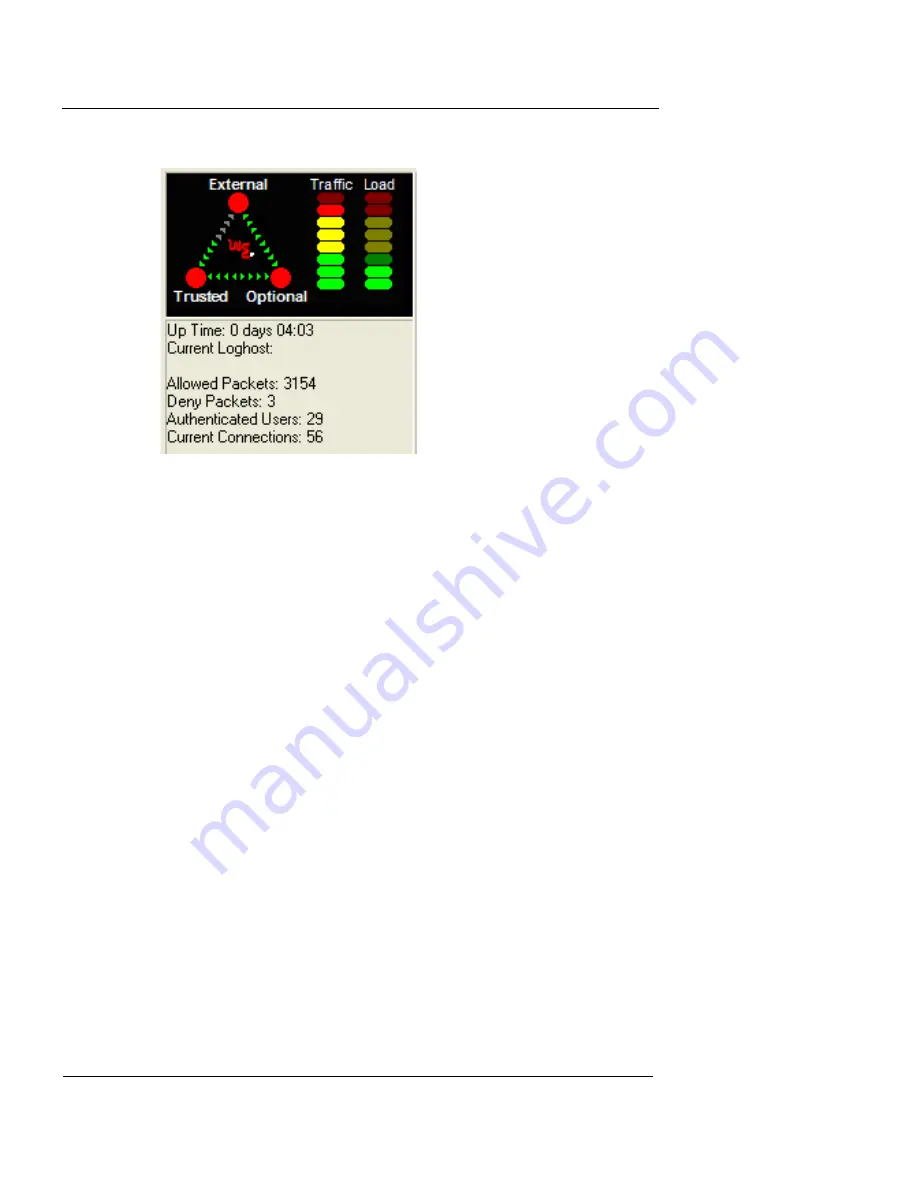
The lights on the display represent those found on the front
panel of the Firebox. The triangle shows the predominant
flows of traffic among the trusted, external, and optional
interfaces. A red corner of the triangle is lit when that inter-
face is blocking packets. The two bar graphs indicate traffic
volume and the proportion of Firebox capacity being used.
For more information on the front panel, see the following
FAQ:
https://support.watchguard.com/advancedfaqs/fbhw_lights.asp
Firebox and VPN tunnel status
The section in System Manager to the right of the front
panel shows the current status of the Firebox and of branch
office and remote user VPN tunnels.
Firebox Status
The following information is displayed under Firebox Sta-
tus, as shown in the following figure:
•
Status of the High Availability option. When properly
configured and operational, the IP address of the
standby box appears. If High Availability is installed
Summary of Contents for Firebox X1000
Page 1: ...WatchGuard Firebox System User Guide WatchGuard Firebox System...
Page 12: ...xii WatchGuard Firebox System...
Page 44: ...Chapter 2 Service and Support 22 WatchGuard Firebox System...
Page 61: ...Cabling the Firebox User Guide 39...
Page 68: ...Chapter 3 Getting Started 46 WatchGuard Firebox System...
Page 78: ...Chapter 4 Firebox Basics 56 WatchGuard Firebox System...
Page 156: ...Chapter 8 Configuring Filtered Services 134 WatchGuard Firebox System...
Page 182: ...Chapter 9 Configuring Proxied Services 160 WatchGuard Firebox System...
Page 220: ...Chapter 11 Intrusion Detection and Prevention 198 WatchGuard Firebox System...
Page 242: ...Chapter 12 Setting Up Logging and Notification 220 WatchGuard Firebox System...
Page 256: ...Chapter 13 Reviewing and Working with Log Files 234 WatchGuard Firebox System...
Page 274: ...Chapter 14 Generating Reports of Network Activity 252 WatchGuard Firebox System...


