background image


XR3D-6 Maintenance & Troubleshooting 

3-2 

EM-XR3D-6-001-EN.D 

©2011 VOTI Inc.


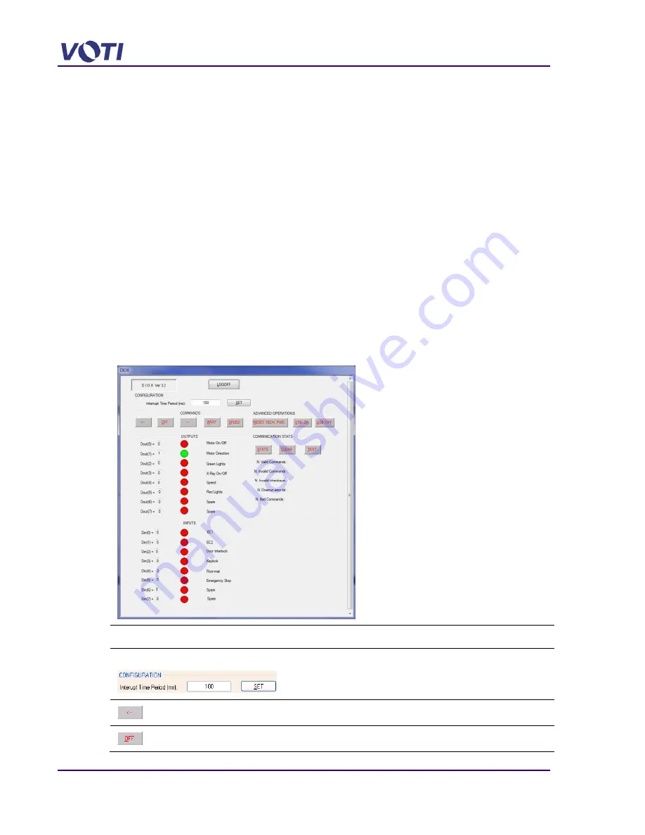
3.2  Check for Digital Inputs Outputs using DIOX  

You  can  either  use  the  Keypad  or  the  DIOX  application  to  verify  there  is  power  going  to  the 
inputs and outputs. To use the DIOX application proceed as follows:  

1.  Verify there is power to the Power Distribution Unit and the UPS (indicated by a Green light). 

These units are accessed by removing the base front access panel. 

2.  Verify  there  is  power  to  the  Computer,  indicated  by  flashing  lights  and  fan  sound  and  the 

cable connections to the 12VDC Components (15-pin connector) is secure.  

The computer is accessed by removing the top left access panel.  

A  VOTI-certified  technician  with  Administrator  permission  can  use  the  DIOX  application  to 
test that the 12VDC components are functional and communicating with the Computer. 

To test the Inputs and Outputs, proceed as follows: 

1.  Log on a VOTI-certified technician using the Administrator permission.  

The Windows

TM

 desktop appears. 

2.  Click on the DIOX shortcut (or go to 

c:\VOTI_Technical_Services\DIOX.exe

) to start 

the DIOX application.  

The DIOX window appears.  


Field 

Description 

Interrupt Time Period (ms) 


Default is 100.  In Milliseconds, this determines how fast the inputs 
are checked and refreshed.  

This setting is only used for the DIOX application test tool.  


Runs the conveyor in a reverse direction.  


Stops the conveyor and X-ray generator action. 

Summary of Contents for XR3D-6

Page 1: ...n whole or in part is prohibited in any form without the prior written permission of VOTI Inc VOTI reserves the right to amend these specifications without notice O XR3D 6 Scanner Maintenance Troubles...

Page 2: ...XR3D 6 Maintenance Troubleshooting ii EM XR3D 6 001 EN D 2011 VOTI Inc...

Page 3: ...2 Check for Digital Inputs Outputs using DIOX 3 2 3 3 Control Box Access Technician 3 4 3 4 Performance Verification Test 3 6 3 4 1 ASTM Test Tool Description 3 6 3 4 2 ASTM Test Tool Placement 3 6 3...

Page 4: ...5 10 5 6 X ray Scan Generation 5 14 5 6 1 Verify the Photo Sensors 5 15 5 6 2 Verify Communication between Control Unit and Computer 5 16 5 6 3 Partial Scanned Image 5 17 5 6 4 15 Pin Connector Compu...

Page 5: ...XR3D 6 Maintenance Troubleshooting EM XR3D 6 001 EN D v 2011 VOTI Inc 7 XR3D 6 Safety Features 7 1...

Page 6: ......

Page 7: ...p Desk Level 2 requires a VOTI trained Technician responsible but is not limited to onsite installations or replacements of various hardware components diagnostic testing and in certain cases Line Rep...

Page 8: ...the operator of the presence of potential threats for example prohibited organic material explosives high density or sharp objects The list of materials can be customized o Organic anything with a car...

Page 9: ...ual Log On as Supervisor Access to Administration Modules Manage Operators Manage Operational Settings An XR3D Administrator has access to the exclusive VOTI diagnostic software used for advanced debu...

Page 10: ...properly installed and maintained and operating as designed the operators are not required to wear personal dosimeters When the XR3D is operated according to design criteria they do not emit detectab...

Page 11: ...personnel must complete training in operation maintenance repair and x ray safety hazards relevant to the x ray inspection system and in x ray safety required by the authority having jurisdiction in...

Page 12: ...UI Graphical User Interface HE High Energy ICRP International Commission on Radiological Protection IED Improvised Explosive Devices IEE Image Edge Enhancement kV Kilo voltage LCD Liquid Crystal Displ...

Page 13: ...the correct power setting for your area proceed as follows 1 Unscrew the front base access panel and lift off the unit This allows access to the back of the Power Distribution box 2 Set the 110 240 to...

Page 14: ...left blue panel ensuring the Monitor Cable Assembly is loose next to the post 5 Slide the articulating arm s on to the monitor post and secure in place using the set screw and an allen key 6 Attach t...

Page 15: ...can be turned by hand To stabilize the unit proceed as follows Tools Level 1 Turn the adjustment wheel to lower the foot 2 Using a level against the base of the XR3D continue to adjust the feet using...

Page 16: ...y starting Message on Keypad VOTI BioSans Enter Password 5 Enter the 4 digit Operator keypad password Do NOT press the Enter button Logging in as a Technician allows you to change passwords for the ke...

Page 17: ...output error nothing else will happen The machine will be prevented from starting up no power until the error is fixed For example o System is Locked appears if you removed the security key while the...

Page 18: ...tor The resulting scan displays in the Main Viewing Screen and alternate views appear in the Alternate Scan View area 4 Check the quality of the image 5 Repeat the scan in the reverse direction 6 Use...

Page 19: ...e log in screen appears on the monitor 2 5 Updating Software The XR3D 6 is shipped from the factory with software pre installed If an update is required it will be provided to the System Administrator...

Page 20: ...XR3D 6 Maintenance Troubleshooting 2 8 EM XR3D 6 001 EN D 2011 VOTI Inc...

Page 21: ...machine has been opened to verify the integrity of the X ray source Seasoning of the X ray Generator Tube Initial installation After any power outage longer than 3 days Calibration Initial installatio...

Page 22: ...he computer is accessed by removing the top left access panel A VOTI certified technician with Administrator permission can use the DIOX application to test that the 12VDC components are functional an...

Page 23: ...e scanner X Ray On Off is for the X ray generator Speed is for the selected speed of the conveyor Red Lights is for the lights on top of the scanner during a scan Spare Not Used Inputs Contains the bi...

Page 24: ...8 Removing the item turns the EC1 indicator GREEN Green means the circuit is open and the switch will not enable the X ray generator 9 Placing and removing an item in the tunnel to block the Photo Sen...

Page 25: ...OFF IS Interlock CLOSE OPEN PS1 Photo Sensor 1 ON OFF PS2 Photo Sensor 2 ON OFF F Floor Mat P N person no person EM Emergency Button NP P no press press 4 Control Outputs Control the outputs for exam...

Page 26: ...previous results recorded on the maintenance log sheet If the results of the tests do not show any significant degradation from the time they were previously run the test cases are considered to be v...

Page 27: ...Set the ASTM test tool on the conveyor belt at the tunnel entrance 3 Click and release the forward arrow on the screen to start the conveyor Indicator lights on the scanner turn red during X ray gene...

Page 28: ...Test Description Result Image Useful penetration determining what the smallest wire gauge you are able to see under aluminum Useful penetration you are looking at the same scan as Test Number 1 but yo...

Page 29: ...ct record on the Log Sheet by checking with a in the box if each layer can be seen any image mode can be used The plastic sample must appear different from the adjacent sample Test Description Result...

Page 30: ...hecking with a in the box if the plastic displays in a different shade or color than the steel any image mode can be used The plastic samples must be seen as a distinct shade or color Test Description...

Page 31: ...le ASTM Log Sheet If the ASTM test does not pass log off and contact the Administrator An Administrator or VOTI certified technician logs on using Administrator permission to access the Windows TM des...

Page 32: ...XR3D 6 Maintenance Troubleshooting 3 12 EM XR3D 6 001 EN D 2011 VOTI Inc...

Page 33: ...n to access the Windows TM desktop 2 Click on DIOX shortcut c Program Files VOTI BioSansXDAQ DIOX exe to start the DIOX application The DIOX window appears 3 Press the XRAY button The lights on the to...

Page 34: ...re enter 1600 and click OK b Click Program Current to set the tube current The unit is 1 A Set the operating current at 100 A therefore enter 1000 and click OK 6 Select Tube Re Seasoning Profile Idle...

Page 35: ...to perform before starting using the unit is to check if the leakage level is still up to the standard This has to be performed by a VOTI trained technician Tests are to be conducted by a Certified Ra...

Page 36: ...led to generate X rays but it is not powered Since the source is not powered there is no radiation emitted 4 Start VOTI s Diagnostic Tool application which is the software for the X ray source located...

Page 37: ...o Click Enable WDT to toggle the display to Disable WDT o Click Disable WDT to toggle the display back to Enable WDT o Click XrayOn 7 Proceed to 3 6 1 Measuring the X rays 3 6 1 Measuring the X rays...

Page 38: ...are any areas on the XR3D 6 that did not pass the test forward the completed Incident and Test reports to Level 3 VOTI technicians at support voti ca 3 7 Calibration Test Procedure To calibrate the XR...

Page 39: ...the X ray source is activated as soon as the conveyor START button is pressed When starting the scan the sensor cannot detect the end of the item so you must press the conveyor STOP button to stop th...

Page 40: ...the calibration The calibration is used to determine the atomic number and a change in the energy results in a change in the calculation Therefore the XR3D must be calibrated if the power is different...

Page 41: ...ata files in c Program Files VOTI BioSansXDAQ Input BIOSANS XData To use the Calibration application proceed as follows 1 Start the Calibration application by clicking C Program Files VOTI BioSansXDAQ...

Page 42: ...est 5 Complete all the Regions by selecting a Regions Delimitation highlighting an area of interest and selecting a different area on each of the steps of the step wedge For example if using Plexiglas...

Page 43: ...otice the Range of Detectors to Calibrate automatically changes and enters the rest of the detectors at the bottom of the screen 12 Complete the Regions Delimitation for the third archive scan for Ple...

Page 44: ...txt 21 Move the new TXT files from the Archive folder and paste them into the Input BIOSANS XData folder 22 After completing the re calibration remove the tape placed over the sensor inside the tunne...

Page 45: ...and X Ray On Off will also turn red It means that the source is enabled to generate X Rays but it is not powered Since the source is not powered there is no radiation emitted 4 Start VOTI s Diagnostic...

Page 46: ...oting 3 26 EM XR3D 6 001 EN D 2011 VOTI Inc 7 Press INACTIVE The button changes to Active 8 Press the Camera icon 9 Select Analysis Column Average 10 Start the X ray with Monoblock by clicking XrayON...

Page 47: ...ource base and move the source back or forward a millimeter or two not much movement is required After adjusting the Source base secure the bolts and re do the test NEVER move the source while it is g...

Page 48: ...XR3D 6 Maintenance Troubleshooting 3 28 EM XR3D 6 001 EN D 2011 VOTI Inc...

Page 49: ...e Replaceable Unit LRU repair Level 3 requires VOTI personnel responsible for handling the most difficult or advanced problems denoting expert level troubleshooting and analysis If one of the followin...

Page 50: ...be taken before attempting to restart the system ERROR MESSAGE PROBABLE CAUSE SOLUTION Error Live Mode not available Configuration File error Level 2 configuration file reset Impossible to capture the...

Page 51: ...irectory not found Disk is almost full Do you wish to make a backup Error deleting the Archive Picture file Administrator settings in the Archive Management tab the disk is almost full and has reached...

Page 52: ...XR3D 6 Maintenance Troubleshooting 4 4 EM XR3D 6 001 EN D 2011 VOTI Inc...

Page 53: ...is clearly marked on the scanner near the power cord External power enters the Power Distribution Unit The circuit breaker at the front of the unit controls power to all the plugs However the plugs l...

Page 54: ...cuit breaker See 5 2 1 Check Keypad Faults Loose 15 Pin Connector pins Check the Keypad for error messages See 3 3 Control Box Access Technician Check Input Output connections See 5 6 4 15 Pin Connect...

Page 55: ...lots See 6 1 Access Interlock Message on the Operator screen Operator not standing on Safety mat or mat Stand on the mat to see if the Interlock message on the Operator screen goes away Check the conn...

Page 56: ...ceed as follows 1 Unplug the AC power cable from the wall receptacle and from the scanner 2 Using a multimeter verify there is voltage on the input AC terminal 3 There should be a reading of either 11...

Page 57: ...aft for the interlock switch 4 Reconnect the mat and stand on the mat to see if this clears the interlock message on the Operator screen If the mat is faulty and there is not a functional mat availabl...

Page 58: ...emoves all VAC power The computer one monitor and all the 12VDC input output components remain powered by the UPS until the emergency stop button is released by turning it clockwise until it pops out...

Page 59: ...The belt tension must be approximately 0 4 1 0 more than the length at rest CONVEYOR TROUBLESHOOTING CHART PROBLEM CAUSE CORRECTIVE ACTION Irregular conveyor movement Test belt tension Try to stop the...

Page 60: ...iver Replace the Motor Driver See 6 8 2 Replace and Setup the Motor Drive 5 4 1 Adjust the Belt Alignment The conveyor drum motor idler and return rollers must be square to the belt motion direction T...

Page 61: ...track the belt to the middle The idler is not crowned and its surface should be identical from edge to edge Tools Hex head socket wrench To re align the belt proceed as follows 1 Remove all power to...

Page 62: ...d 1 Verify that the drums are turning 2 Verify the Conveyor Belt moves in both directions If the Conveyor Motor only moves in one direction the Motor must be replaced See 6 8 2 Replace and Setup the M...

Page 63: ...ernet not used H 15 Pin Connector to Keypad Control Unit Computer TROUBLESHOOTING CHART PROBLEM CAUSE CORRECTIVE ACTION No video from the computer Monitor cable is defective or not connected properly...

Page 64: ...monitor functionality is hung up Check the power indicator light at the monitor and check the monitor cables Check the monitor USB cable at the Computer for the touch screen functionality Reset the To...

Page 65: ...Name BiosansAdminMenuX X XXX exe string BioSansExecName BioSansXDAQX X XXX exe Error Message Problem Communicating with DIO Configuration file is corrupt or missing the COM Port value that is set in t...

Page 66: ...one given by the device manager 3 Set the value and save the file 4 Restart the Computer using the toggle switch at the left base panel 5 Use the DIOX application and verify the X ray outputs Hard dis...

Page 67: ...on cable connections If only the top of the image appears check the ribbon cable connections of the TOP detectors If only the bottom of the image appears check the ribbon cable connections of the SIDE...

Page 68: ...rror when connecting to the detectors If the software cannot start and displays Communication problem with the Detectors 1 Log in as a VOTI Trained Technician using the Administrator permission to acc...

Page 69: ...nned Image If when doing a scan only part of the image appears check the ribbon cable connections If only the top of the image appears check the ribbon cable connections of the TOP detectors If only t...

Page 70: ...fy the 12VDC power at the 15 pin Connector pins Pin Definition Color Direction 1 Red LED Red Output 2 Green LED Green Output 3 Motor Start Blue Output 4 Motor Speed Green Yellow Output 5 Motor Directi...

Page 71: ...e image on view screen Configuration file problem Buffer set too high Computer prompts detectors to provide a second image Reset the size of the buffer 2560 lines for dual view and 1218 lines for a si...

Page 72: ...e to ensure a live picture is displayed 2 Ensure there is no item in the tunnel As long as there is no item in the tunnel to trigger the sensor X rays are not generated 3 Verify the camera LED is oran...

Page 73: ...s make sure that the power is turned OFF preferably at the wall receptacle and at the UPS Attach a Do Not Operate tag to the AC plug or the Operator Key Switch Do not touch the terminals or other curr...

Page 74: ...ed through the top security access panel Tools Screwdriver with Security Chuck 10mm Hex head socket wrench 1 Unplug the scanner power cable from the wall receptacle 2 Using a screwdriver with the secu...

Page 75: ...wrench loosen and remove 2 bolts on either side of the computer 8 Unplug the 15 pin connector and the connectors to the monitor and the UPS 9 Unscrew 2 screws securing the computer top access panel a...

Page 76: ...cess panel and the base front and back access panels The system restarts 6 3 Replace the Detectors To access the Detectors the Rear Base Panel Rear Tunnel Cover Tunnel Top Access Panel the Detector To...

Page 77: ...els 6 Gently pull out the rear tunnel panel cover to unlatch the cover from the bottom then lift top off the securing latches 2 per panel 7 Remove the rear tunnel panel cover 8 Loosen and remove 4 bol...

Page 78: ...r group if required 11 Remove 2 side bolts holding the Top and the Side Detector groups together 12 Remove the lead sheath carefully setting it aside to be reused on the new detector groups 13 Unplug...

Page 79: ...Shaft B Butterfly Clip 2 C NO Normally Open Terminal D Common Terminal E Butterfly Clip 2 5 Label and remove the wires 6 Squeeze the butterfly clip of the new switch and push the switch in place with...

Page 80: ...he OFF position 10 Plug in the power cable at the wall receptacle and turn flip the XR3D circuit breaker to the ON position 11 Verify the computer and the 12VDC components start 6 6 Remove and Replace...

Page 81: ...ss the UPS Power button to ensure the UPS turns on and the UPS LCD Display illuminates 11 Replace and secure the front access panel 6 7 Remove and Replace the Emergency Stop Switch There is an Emergen...

Page 82: ...the top of the scanner 10 Secure in place with the locking ring and tighten hand tight 11 Insert the wires into the terminal block and screw in place 12 Align the terminal block the knob and gently t...

Page 83: ...idler end of the conveyor Push in the conveyor idler to release the belt tension 7 Put a weight on the belt to stop it from sagging into the base of the XR3D If the conveyor belt does not need replac...

Page 84: ...oceed as follows 1 Access the conveyor rollers by opening the access panel either front or back 2 Thread a new belt through the scanner rollers taking care when feeding it through the rollers in the b...

Page 85: ...huck remove the 2 or 4 security screws M6 x 25 SS machine screw with a 6 point security head on the base front to access the UPS and rear access panel 3 Turn off the UPS by pressing the power button 4...

Page 86: ...cation 104 6 Press M for the contents and use the arrows to set this location to 5 and press M again to accept the entry 7 Press M again until 100 displays then use the arrow to go to location 105 8 P...

Page 87: ...ug the scanner power cable from the wall receptacle 2 Using a screwdriver with the security chuck remove the 2 or 4 security screws M6 x 25 SS machine screw with a 6 point security head on the base fr...

Page 88: ...andards as per the reporting sheets the x ray source may be degraded and may need changing To remove and replace the X ray source proceed as follows Tools Screwdriver with Security Chuck 10mm Socket W...

Page 89: ...ital Signal Interface JB5 connector at the X ray Source 6 Push the locking tab and unplug the 7 Pin Molex Connector at the X ray Source 7 From the back access panel unbolt four 4 bolts securing the fu...

Page 90: ...oubleshooting 6 18 EM XR3D 6 001 EN D 2011 VOTI Inc 10 Undo six 6 bolts and remove the funnel and put it aside 11 Remove the funnel gasket and put it aside 12 Unbolt the X ray Source from the base by...

Page 91: ...Error Reference source not found 10 Perform the X ray Alignment test 3 8 Realign the X ray Source 11 Bolt the X ray Source bracket into place 12 Press the UPS power button to turn the UPS power suppl...

Page 92: ...pad box to the right side of the XR3D frame 7 Position a new Keypad control box and secure to the XR3D frame using two 2 bolts 8 Plug the 15 pin and the 2 pin Molex connectors and the Secure USB and C...

Page 93: ...ut there are no X rays being generated Red lights indicate the scanner is generating X rays Emergency Shut Off The Emergency Stop buttons remove power from the X ray source and conveyor Depressing one...

Page 94: ...he power input Should AC power be cut the UPS supplies power to the computer and the monitors for at least 5 seconds to safely shut down the system ensuring all data is saved Circuit breakers disconne...

Reviews: