XR3D-6 Maintenance & Troubleshooting
5-18
EM-XR3D-6-001-EN.D
©2011 VOTI Inc.
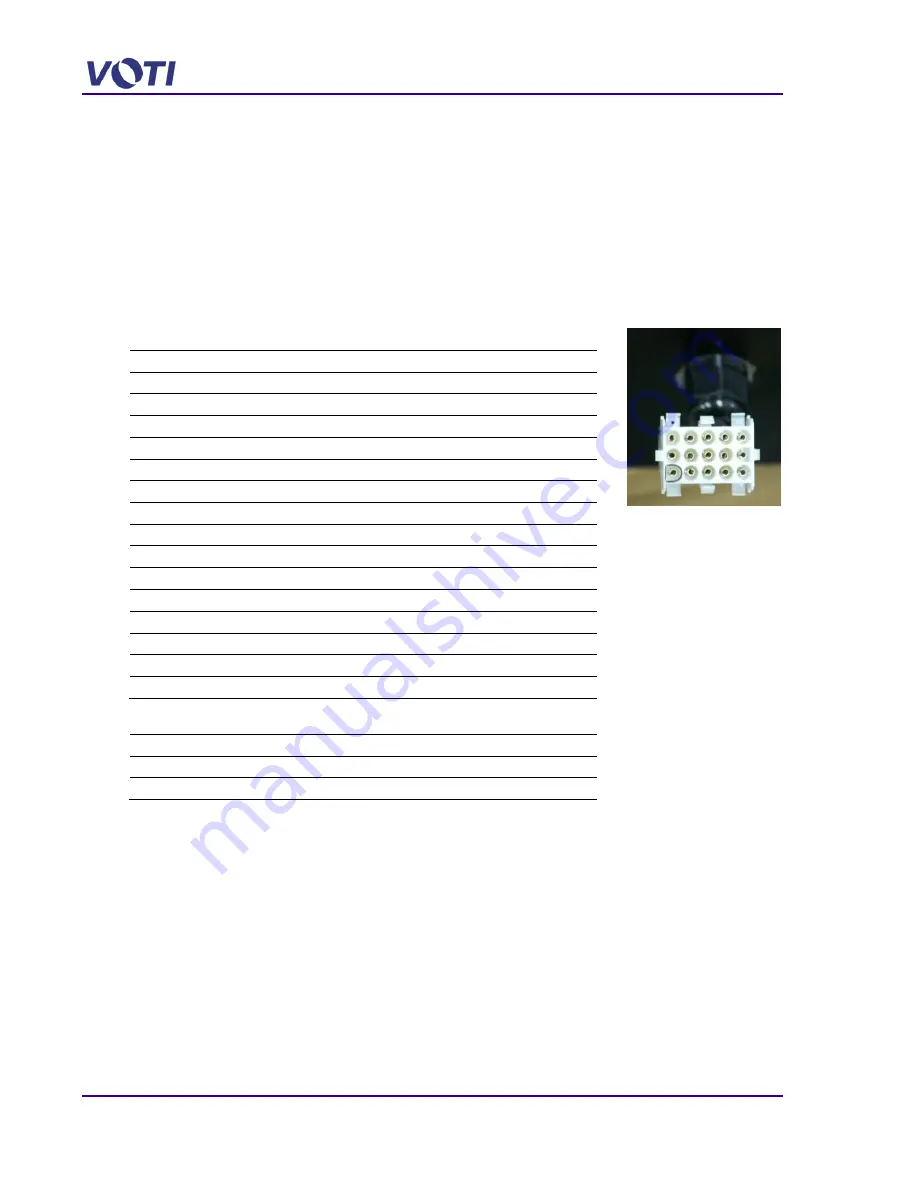
5.6.4 15-Pin Connector / Computer and Input/Outputs
If there is no communication between the Control Unit (Keypad) and the Computer, proceed as
follows:
1. Open the Front Tunnel Access Panel to check the power cable (15-pin connector) to the
12VDC Components.
The power cable assembly comes from the keypad to the computer (12VDC Components).
2. Ensure that the 15-pin connector is securely connected.
3. If the cables are secure, reboot and restart the computer to see if this clears the problem.
4. Verify the 12VDC power at the 15-pin Connector pins.
Pin
Definition
Color
Direction
1
Red LED
Red
Output
2
Green LED
Green
Output
3
Motor Start
Blue
Output
4
Motor Speed
Green/Yellow
Output
5
Motor Direction
Violet
Output
6
X-Ray Gate
Gray
Output
7
PC Button
Brown
Output
8
NA
9
Interlock
White or Yellow
Input
10
Photo Sensor 2
Orange
Input
11
Photo Sensor 1
Blue
Input
12
Emergency Button
Black
Input
13
Floor mat
Yellow
Input
14
Ground Output
Black
Output
15
12 Volts Output
Red
Output
5. Verify the 12VDC power at the 2-pin Connector pins.
Pin
Definition
Color
Direction
1
Ground Input
Black
Input
2
12 Volts Input
Red
Input
6. Use the DIOX application to verify the functionality of the inputs and outputs. Refer to
Summary of Contents for XR3D-6
Page 2: ...XR3D 6 Maintenance Troubleshooting ii EM XR3D 6 001 EN D 2011 VOTI Inc...
Page 6: ......
Page 20: ...XR3D 6 Maintenance Troubleshooting 2 8 EM XR3D 6 001 EN D 2011 VOTI Inc...
Page 32: ...XR3D 6 Maintenance Troubleshooting 3 12 EM XR3D 6 001 EN D 2011 VOTI Inc...
Page 48: ...XR3D 6 Maintenance Troubleshooting 3 28 EM XR3D 6 001 EN D 2011 VOTI Inc...
Page 52: ...XR3D 6 Maintenance Troubleshooting 4 4 EM XR3D 6 001 EN D 2011 VOTI Inc...


