


G413 User Guide Document: G41302
-------------------------------------------------------------------------------------------------------------------------------------------
1
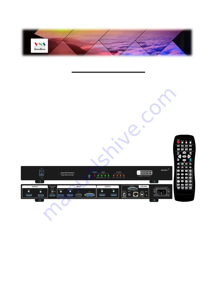
G-413 User Guide
Quad channel creative video wall controller
25 editable preset display modes
Custom modes with LCD at any angle and position
PIP/POP
Multi-unit cascade
Flexible aspect ratio and display region adjustment
Seamless looping playback with different display modes
RC-400
The absolute opposite of ordinary


