background image

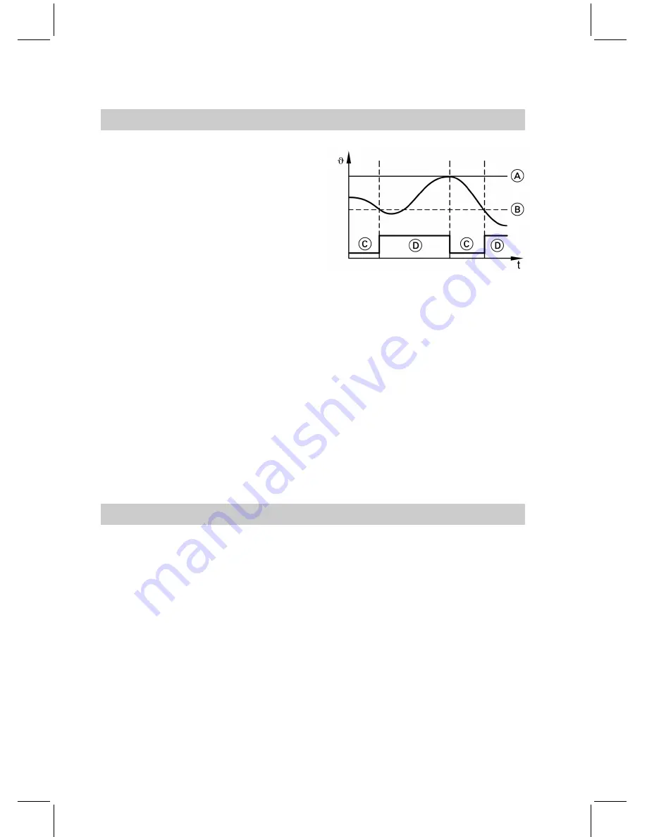
This setting determines, at what
deviation from the selected set tem-
perature the cylinder heating starts or
stops.

Note

If a low loss header is being used,
enter a higher setting

here

than the

one in "Flow hysteresis" (see
page 94).

A

Set temperature

B

Start hysteresis

C

Cylinder heating OFF

D

Cylinder heating ON

Access

&

"

System settings

"

&

"

Program

"

&

"

Buffer storage

"

&

"Hysteresis T top "

(

1

/

!

)

Standard setting

5 K

Setting range

2 to 20 K

Maximum temperature

Setting of the maximum temperature
in the heating water buffer cylinder.

Access

&

"

System settings

"

&

"

Program

"

&

"

Buffer storage

"

&

"max. temperature"

(

1

/

!

)

Standard setting

60 °C

Setting range

1 to 70 °C

Hysteresis temperature

116

Buffer cylinder control settings

55

92

901

GB

Summary of Contents for VITOCAL 300

Page 1: ...VIESMANN Installation and service instructions for contractors Vitocal 300 Vitocal 300 type BWC and WWC For applicability see the last page VITOCAL 300 5592 901 GB 6 2007 Please keep safe...

Page 2: ...legal instructions regarding the prevention of accidents all legal instructions regarding environmental protection the Code of Practice of relevant trade associations all current safety regulations a...

Page 3: ...loads Repair work Please note Repairing components which fulfil a safety function can com promise the safe operation of your heating system Replace faulty components only with original Viessmann spare...

Page 4: ...primary side 38 Connections on the heating circuit side 39 Power supply 39 Service instructions Commissioning inspection maintenance Steps commissioning inspection and maintenance 41 Further details...

Page 5: ...FF 89 Electric heating 89 Electric DHW heating 89 Maximum flow temperature 90 Heater rod delay 90 Electric heater threshold 90 Maximum stage electric heater 91 Power failure blocking time 91 Failure O...

Page 6: ...perature sensor 105 Slope room temperature hook up 105 Room temperature hook up 105 Start optimisation 106 Maximum flow temperature correction 106 Room temperature control 107 Setting the slope and le...

Page 7: ...m temperature controller 120 Minimum flow temperature 120 Natural cooling with mixer 120 Cooling mixer runtime 121 Mixer active zone dead zone 121 Control settings external heat source External heat s...

Page 8: ...chain 135 Control PCB 137 Parts lists 139 Commissioning service reports Hydraulic parameter reports 142 Reports of control parameters 143 Specification type BWC 149 Specification type WWC 151 Appendi...

Page 9: ...w of possible system versions In the following 3 typical heat pump system designs are shown by way of an example The heating system installation also applies to Viessmann heat pumps type WWS comprisin...

Page 10: ...2 X X X X X X X X X 3 X X X 4 X X X X 5 X X X X X X X X X 6 X X X X X X X X X X F The Vitocal 300 responds only to external demand signals All exter nal sensors e g room temperature sensors and relay...

Page 11: ...longer idle periods standby mode during holi days heating circuit pumps in sum mer all pumps directly controlled by the heat pump control unit are started for 10 s every day at 13 00 h Low loss heade...

Page 12: ...ds the cooling temperature limit which can be adjusted at the control unit The primary pump starts and the cooling circuit pump the three way diverter valve heating cooling and the solar circuit shut...

Page 13: ...he first cylinder temperature sensor Protect the immersion heater via a separate connection The contactor is controlled by the heat pump control unit Blocking Power OFF Implement the heat pump blockin...

Page 14: ...type BWC with integral primary pump 2 secondary pump 3 and electric heater 4 1 5 Ground probe or ground collector min 1 6 Brine distributor for ground probes or collectors 1 7 Brine pressure switch op...

Page 15: ...ion diagram 8 Inserting the jumper or connecting the brine pressure switch 9 Optional connection of a power OFF conversion kit System design on the primary side cont 15 Preparing for installation 5592...

Page 16: ...circuit Please note Operating the intermediate circuit without antifreeze can result in equip ment damage Fill the intermediate circuit with heat transfer medium frost protection down to 15 C System d...

Page 17: ...pump as required qP Dirt trap 1 qQ Volume choke 1 qW Intermediate circuit heat exchanger 1 qE Brine pressure switch for intermediate circuit option 1 qZ Contactor on site for switching the primary pu...

Page 18: ...ling at the heating circuit Note Select system design 2 at the control unit A Connection at the primary side see from page 14 B DHW cylinder connection see from page 30 D Minimum clearance 500 mm Syst...

Page 19: ...Connection diagram Open CLOSE System version 1 cont 19 Preparing for installation 5592 901 GB...

Page 20: ...ct heating circuit underfloor heating circuit qO Temperature limiter only required for the underfloor heat ing circuit as required rO Zero volt contact for central fault messaging acoustic or optical...

Page 21: ...cylinder and natural cool ing for the heating circuit with mixer Note Select system design 6 at the control unit A Connection at the primary side see from page 14 B DHW cylinder connection see from pa...

Page 22: ...Connection diagram Open CLOSE System version 2 cont 22 Preparing for installation 5592 901 GB...

Page 23: ...ing circuit pump direct heating circuit 1 wW Heating circuit pump of the heating circuit with mixer 1 wE Mixer 3 heating circuit with mixer 1 wO Flow temperature sensor for mixer 3 wE 1 rO Zero volt c...

Page 24: ...d nat ural cooling at the heating circuit with mixer Note Select system design 6 at the control unit A Connection at the primary side see from page 14 B DHW cylinder connection see from page 30 C Exte...

Page 25: ...imum clearance 500 mm E The flow rate on the heating cir cuit side must be greater than the flow rate on the secondary side of the heat pump System version 3 cont 25 Preparing for installation 5592 90...

Page 26: ...Connection diagram Open CLOSE A External heat source System version 3 cont 26 Preparing for installation 5592 901 GB...

Page 27: ...required wQ Heating circuit pump direct heating circuit 1 wW Heating circuit pump mixer circuit 1 wE Mixer 3 heating circuit with mixer 1 wO Flow temperature sensor for mixer wE 1 rO Zero volt contact...

Page 28: ...ve 1 rE Natural cooling extension kit 1 Additions to the system versions Separate cooling circuit for natural cooling A Connection on the primary side see from page 14 D Minimum clearance 500 mm E Con...

Page 29: ...tion pump primary cooling circuit pump 1 wU Mixer 3 primary cooling circuit 1 1 wI Two way motorised ball valve 1 eQ Circulation pump secondary cooling circuit pump 1 eW Diaphragm expansion vessel 1 r...

Page 30: ...Direct DHW heating A from the heat pump KW Cold water WW DHW Additions to the system versions cont 30 Preparing for installation 5592 901 GB...

Page 31: ...er valve heating DHW 1 eE Vitocell V 100 type CVW 390 litre capacity 1 eZ Cylinder temperature sensor top 1 rP Spring loaded check valve 1 rW Immersion heater EHO installation either at the top or bot...

Page 32: ...at pump terminal strip 230 400 V connections inside the open control panel C Electronics PCB D Back of the pivoted control panel E PCB with terminal strip X1 X2 Room temperature sensor part no 9532 65...

Page 33: ...sen sor for the direct heating circuit heating circuit 1 X1 14 X2 14 F6 Room temperature sen sor for the heating cir cuit with mixer heating circuit 2 X1 6 X2 6 F16 Room temperature sen sor for natura...

Page 34: ...spring loaded return N Neutral conductor Earth conductor 32 Control signal OPEN without spring loaded return N Neutral conductor Earth conductor 32 Control signal OPEN 33 Control signal CLOSE Three wa...

Page 35: ...pump only for type WWC For the Vitocal 300 type WWC the integral pump provides the circulation in the intermediate circuit Provide and wire the primary pump on site The control signal for the contact...

Page 36: ...stallation D Primary pump on site Information regarding the hydraulic connection To ensure perfect operation route brine circuit pipes so that no air pockets can form and complete ven tilation is ensu...

Page 37: ...he blow off and drain pipes should terminate in a container capable of holding the max possible expansion volume The components used must be resistant to the heat transfer med ium never use zinc plate...

Page 38: ...B Primary flow brine or ground water Route and connect the flow and return lines Vitocal 300 Type BWC WWC 104 106 108 110 Primary flow R 1 1 1 1 Primary return R 1 1 1 1 Connection on the primary sid...

Page 39: ...njury through the transmission of dangerous body currents and result in equipment damage Carry out the power supply connection and all earthing measures i e RCD circuit in accordance with IEC 364 the...

Page 40: ...he back into the heat pump and con nect it in accordance with the dia gram Please note To prevent equipment damage never interchange cores A clockwise field of rotation is absolutely required Note Hea...

Page 41: ...ntermediate circuit and checking the pressure 45 9 Checking the connections at terminals 1 and 2 as well as 5 and 6 10 Checking the tightness of electrical connections 11 Isolate the compressor Discon...

Page 42: ...52 25 Checking the antifreeze concentration in the brine circuit type BWC and WWC with intermediate circuit 54 26 Checking the frost stat type WWC 54 27 Checking the flow switch type WWC 54 28 Checki...

Page 43: ...ble solder joints for traces of oil Fill the system and check for leaks 1 Open any fitted non return valves 2 Check the inlet pressure of the dia phragm expansion vessel 3 Thoroughly flush the heating...

Page 44: ...illing pressure exceeds the inlet pres sure of the diaphragm expansion vessel On a cold system the filling pres sure must be approx 0 2 bar higher than the static pressure Max operating pressure 4 bar...

Page 45: ...t if required see page 43 Checking the input terminals and contactors Check the voltage and cycle at the power supply at the input terminals and at the contactors Voltage 400 V 3 Rotating field clockw...

Page 46: ...ss the key marked in the dia gram 4 Press the following keys one after the other v O and Enter the code for heating con tractors SERVICE for details see page 76 Press the following keys one after the...

Page 47: ...programming unit flap see page 57 and operating instruc tions and briefly and simulta neously press the keys shown in the diagram Note Alternative adjustment options for the system design see page 80...

Page 48: ...levant component is not yet selected if the key function YES is displayed If you then press the key the com ponent will be selected and the key function changes to NO You can deselect that component b...

Page 49: ...ther menu items Heat circuit 1 pump or Heat circuit 2 pump if installed Note The time elapsed since the start of the test program is shown in the top r h corner of the display Further more the status...

Page 50: ...nections Select a different pump stage or use an external pump 3 Start the compressor by pressing ON 4 Check the primary pump Determine the temperature differ ential T between the primary inlet displa...

Page 51: ...ions of the three way valve Replace the three way valve if required The temperature at Secondary flow must rise observe a rise up to approx 30 C Otherwise Check the primary pump Check the electrical c...

Page 52: ...y test of the control unit see page 79 the mixer is set to Open and Close Changing the rotational direction Turn plug A by 180 Manual mixer adjustment Lift and disengage the mixer han dle Rated voltag...

Page 53: ...or this installation example The mixer insert must be converted see mixer installation instructions A Marking notch B Heat pump flow HR Heating return HV Heating flow The rotational direction of the m...

Page 54: ...ressor Menu item System settings Tech service level possibly enable see page 77 Manual control Switch relay With RESET set all relays to OFF Use keys x and y to select Primary pump and enable with ON...

Page 55: ...vate the Tech service level For information regarding the Tech service level and regard ing control parameters see chap ter Control settings from page 65 2 Check the control settings using the details...

Page 56: ...might have been drilled into the casing cable entries with permanently flexible sealant to prevent condensate forming in the heat pump interior Further details regarding the individual steps cont 56...

Page 57: ...t is closed the fault symbol U flashes on the control unit display A maximum of 8 faults can be stored Messages with lower priority will be deleted if there are messages with higher priority than thos...

Page 58: ...n removed Press OK to acknowledge the highlighted fault message Press ALL to acknowledge all fault messages Scanning fault messages There are two different options for scanning fault messages Scanning...

Page 59: ...als replace the sensor if required 20 Sec flow sensor Short circuit Check the sensor replace if required 28 Sec flow sensor Lead broken Check the terminals replace the sensor if required 30 Primary in...

Page 60: ...or bot tom 60 Buffer cylinder sensor Short circuit Check the sensor replace if required 61 Secondary return sensor 62 Buffer cylinder bottom 63 Ext heat source 64 Mixer ext heat source 68 Buffer cylin...

Page 61: ...y cut out possibly reset the high limit safety cut out see page 63 AC Natural cooling Faulty function As part of the relay test see page 79 check the natural cooling connection exten sion and the cont...

Page 62: ...ary pump Thermal overload relay of the primary pump has responded Reset the thermal overload relay check the primary pump see page 50 and re place it if required CB Primary tempera ture Primary inlet...

Page 63: ...oom tempera ture sensor HC 2 Reset the high limit safety cut out Please note Touching live components in the working area can result in the transfer of dangerous body currents Ensure the device is at...

Page 64: ...of the heating circuit s concerned 7 Enable the heating operation via the integral electric heater see page 89 No indication on the programming unit display Carry out the following steps in the order...

Page 65: ...A See page 66 B See page 67 C see pages 68 to 70 D see pages 71 to 75 Menu structure overview Main menu 65 Control unit settings 5592 901 GB Service...

Page 66: ...Main menu Information A See page 67 Menu structure overview Information 66 Control unit settings 5592 901 GB...

Page 67: ...Main menu Information A See page 66 Menu structure overview Information cont 67 Control unit settings 5592 901 GB Service...

Page 68: ...Main menu Device settings Programming A See page 69 B See page 70 Menu structure overview Programming 68 Control unit settings 5592 901 GB...

Page 69: ...Main menu System settings Programming A See page 68 B See page 70 Menu structure overview Programming cont 69 Control unit settings 5592 901 GB Service...

Page 70: ...Main menu System settings Programming A See page 68 B See page 69 Menu structure overview Programming cont 70 Control unit settings 5592 901 GB...

Page 71: ...Main menu Device settings Technical service level A see pages 74 and 75 B see pages 72 and 73 Menu structure overview Technical service level 71 Control unit settings 5592 901 GB Service...

Page 72: ...Main menu System Settings Technical service level A See page 71 B see pages 74 and 75 C See page 73 Menu structure overview Technical service level cont 72 Control unit settings 5592 901 GB...

Page 73: ...Main menu System settings Technical service level A See page 71 B see pages 74 and 75 C See page 72 Menu structure overview Technical service level cont 73 Control unit settings 5592 901 GB Service...

Page 74: ...Main menu System settings Technical service level A see pages 71 to 73 B See page 75 Menu structure overview Technical service level cont 74 Control unit settings 5592 901 GB...

Page 75: ...Main menu Device settings Technical service level A see pages 71 to 73 Menu structure overview Technical service level cont 75 Control unit settings 5592 901 GB Service...

Page 76: ...our warranty The description of the control unit set tings on pages 71 to 125 is structured as follows Descriptions of the Tech service level menu see also pages 71 to 75 are listed on pages 76 to 79...

Page 77: ...al service level Adjusting sensor temperatures Sensor deviations caused by differing line resistances can be compensated for using this function Data remains stored even during power failures Menu ite...

Page 78: ...l control functions are disabled as long as the Manual control menu or one of its sub menus is called up All actuators can only be controlled manually for as long as the program ming unit flap remains...

Page 79: ...every operating procedure then set the required actuators to On Menu item System settings Tech service level Manual control Switch relay The RESET key switches all relays OFF that are currently switc...

Page 80: ...the heating curve and for defining the heating period Independent of this value an average value is formed every 10 min to safe guard the frost protection of the sys tem This value remains unchanged...

Page 81: ...g range 0 to 20 K Temperature limit for reduced temperature mode The reduced temperature mode see operating instructions setting switching times will no longer be used if the average outside tempera t...

Page 82: ...temperature can be selected C Frost protection OFF point frost protection temperature 2 K D Reduced heating mode OFF E Reduced heating mode ON Access System settings Program System definition Frost p...

Page 83: ...ystem settings Program System definition Prim pump ON at NC YES NO Standard setting Yes Setting range Yes No Primary pump ON for natural cooling cont 83 System definition control settings 5592 901 GB...

Page 84: ...the secondary side The electric heater stays ON until the minimum return temperature has been reached Note The compressor wear will increase through more frequent low pressure shutdowns if the minimu...

Page 85: ...d setting Setting range Hyst primary temp 5 K 1 to 20 K min T brine entry 4 C 10 to 20 C Minimum runtime Setting the minimum heat pump run time The heat pump will only stop after expiry of this time T...

Page 86: ...s Program Heat pump min compressor off P Q Standard setting 10 00 min Setting range 00 20 to 30 00 min Flow primary secondary pump When the compressor starts the pri mary and the secondary pumps must...

Page 87: ...mp Flow primary pump or Flow secondary pump P Q Standard setting 2 00 min Setting range 00 10 to 16 40 min Optimum runtime Setting the optimum heat pump run time Excessive runtimes subject to the prim...

Page 88: ...ge B Icing up of the probe C Optimum runtime Access System settings Program Heat pump Optimal op time P Q Standard setting 2 00 h Setting range 00 20 to 18 00 h Optimum runtime cont 88 Heat pump contr...

Page 89: ...ng of the heating circuit tem perature by the electric heater Access System settings Program Electric heating Heating with electro YES NO Standard setting YES Setting range YES NO Electric DHW heating...

Page 90: ...heat rod P Q Standard setting 0 30 h Setting range 0 00 to 5 00 h Electric heater threshold This setting determines after what value integral comprising the dura tion and level of a temperature devia...

Page 91: ...ing for the delay for re enabling the electric heater after a power fail ure or power shut off Note The blocking time is also effective after the system has been manually switched OFF and back ON agai...

Page 92: ...ic heater to which the power OFF applies The power OFF applies to the selected stage and next higher stage Output stages 1 2 and 3 correspond to a respective output of 3 6 and 9 kW Access System setti...

Page 93: ...or drying buildings Setting of the number of days that the system should provide heat for drying buildings Heating is provided at the maximum flow temperature of the heating circuit see page 103 The 0...

Page 94: ...ow setting defines at what difference from an internally calculated set flow tempera ture one of the heat sources heat pump electric heater is switched ON and OFF Access System settings Program Intern...

Page 95: ...and lower cylinder temperature sensors Fixed value Operation as fixed value controller with a selected set tempera ture 2 for the DHW Rotary se lector The settings of the operating mode selector and...

Page 96: ...tion on site Access System settings Program DHW HW buf storage max T U Standard setting 60 C Setting range 20 to 80 C Hysteresis DHW electric heater hysteresis These settings determine at what deviati...

Page 97: ...eresis should be higher than the expected temperature drop due to heat losses in a single night approx 5 K A lower value for Hyst HW e heat ing increases the proportion of elec trical DHW heating i e...

Page 98: ...om The DHW cylinder can be used more efficiently if the DHW cylinder that is used allows a second temperature sensor to be installed further down This temperature sensor is used as a reference point i...

Page 99: ...he excess heat being created is not critical for the heat pump Access System settings Program DHW Reaction overplus l m Standard setting 2 Setting range 0 to 2 DHW priority When DHW priority has been...

Page 100: ...rity is enabled The DHW cylinder will still be heated first in case of demand if after expiry of this time there is still a heat demand from the heating circuit Access System settings Program Heat pum...

Page 101: ...ted in this menu if an immersion heater is used in the DHW cylinder to enable the control unit to switch the immersion heater Note The electric heater element is not switched OFF during a power OFF Ac...

Page 102: ...oom temperature sensor in the remote control The remote control offers no possibility of changing the heating programs or the temperature Access System settings Program Heating circuit Heating circuit...

Page 103: ...e heating circuit flow tem perature to a maximum value The lowest available value represents the setting of the value for min flow temp see page 103 Access System settings Program Heating circuit Heat...

Page 104: ...y YES NO Standard setting YES Setting range YES NO Excess reaction Coordination of the heat drawn off in the secondary circuit when the heat pump produces an excess of heat or the heat drawn by the se...

Page 105: ...ctivated see page 105 and room temperature hook up being enabled see page 105 The higher the selected value the greater the influence of the room tem perature Access System settings Program Heating ci...

Page 106: ...ximum flow temperature correction Prerequisites Room temperature sensor installed and enabled see page 105 Setting the maximum value by which the flow temperature can be modified through the room temp...

Page 107: ...m temperature control Access System settings Program Heating circuit Heating circuit 1 2 Room control YES NO Standard setting NO Setting range YES NO Setting the slope and level of the heating curve O...

Page 108: ...e This function selects the temperature rise of the secondary circuit over that of the mixer circuit subject to a mixer circuit being connected Access System settings Program Heating circuit Heating c...

Page 109: ...ating circuits are connected Please note High flow temperatures can result in screed damage Observe the screed manufac turer s instructions regarding the permissible flow tempera tures Note Observe th...

Page 110: ...dead zone C determines the fluctuation range around the set flow temperature in which the mixer does not respond is at zero volts As soon as the flow temperature leaves this zone above or below the mi...

Page 111: ...2 0 to 40 0 K Heat mix non op band 1 0 K 0 5 to 3 0 K natural cooling at the heating circuit If all on site components for the nat ural cooling function are installed at the heating circuit see page 1...

Page 112: ...resis of 1 K A Set room temperature B Cooling limit temperature C Selected value Cooling limit T room D Average outside temperature E Cooling function ON F Cooling function OFF Access System settings...

Page 113: ...ooling curve 1 2 0 0 to 3 5 Natural cooling at the heating circuit with mixer Select Yes for this setting if a mixer is used for the natural cooling func tion The primary cooling pump can be switched...

Page 114: ...time Setting of the time required by the ser vomotor of the cooling mixer for a complete changeover from one oper ating state into another 90 degree movement Runtimes that are too short can lead to th...

Page 115: ...System settings Program Buffer storage Buffer storage YES NO Standard setting NO Setting range YES NO Buffer cylinder program Operating instructions Vitocal 300 Fixed temperature Note The temperature...

Page 116: ...Start hysteresis C Cylinder heating OFF D Cylinder heating ON Access System settings Program Buffer storage Hysteresis T top 1 Standard setting 5 K Setting range 2 to 20 K Maximum temperature Setting...

Page 117: ...eratures were reached in the heat pump circuit or the minimum heat pump runtime has not yet been reached 2 Heat will be drawn off even if the excess heat being created is not critical for the heat pum...

Page 118: ...If it was not select option Yes here Note If the system is equipped with a sepa rate natural cooling circuit never beforehand select Yes under Device settings Programming Heating circuit 1 2 for natu...

Page 119: ...nitude to regulate the room temperature If room temperature dependent con trol is required select option Yes here If weather compensated control is required select option No here Access System setting...

Page 120: ...a minimum value Access System settings Program Natural Cooling min flow temp 1 Standard setting 10 C Setting range 1 to 30 C Natural cooling with mixer Select Yes for this setting if a mixer is used...

Page 121: ...tural Cooling Cooling mixer runtime m l Standard setting 0 10 minutes Setting range 0 05 to 4 15 min Mixer active zone dead zone For function description see page 110 Access System settings Program Na...

Page 122: ...stem settings Program Ext heat source Priority ext HS YES NO Standard setting YES Setting range YES NO Temperature limit for operation Setting of the temperature limit for the additional operation of...

Page 123: ...ysteresis D Value integral Access System settings Program Ext heat source Threshold ext heat source P Q Standard setting 300 Setting range 10 to 3000 Delay external heat source This setting defines th...

Page 124: ...the external heat source can be can celled by the control unit after this per iod has expired The runtime must not be less than the specified minimum Access System settings Program Ext heat source Min...

Page 125: ...ternal heat source compared to the set flow temperature of the heating circuit Access System settings Program Ext heat source T flow excess 1 Standard setting 0 K Setting range 20 to 20 K Power OFF Th...

Page 126: ...temperature sen sor and flow temperature sensor Fuse The fuse is located in a fuse base on the mounting rail inside the control panel Fuse 6 3 A slow 250 V max power loss 2 5 W A Fuse holder with fuse...

Page 127: ...erminal strip X50 at the back of the connection array It monitors the com pressor power supply feed Two versions may be used The following alternatives are set up in the delivered condition Over under...

Page 128: ...LEDs explained LED Rel illuminates green All voltages and the rotating field clockwise are healthy LED Ph illuminates red The relay has responded the rotat ing field is anti clockwise All LED s off On...

Page 129: ...responded the rotat ing field is anti clockwise All LED s off One or several phases has have dropped out LED U flashes yellow Undervoltage on one several phase s LED U illuminates yellow Overvoltage...

Page 130: ...rce or primary cooling circuit X1 10 2 10 F13 Flow mixer circuit 2 Heating circuit with mixer X1 9 2 9 F14 F15 Heating water buffer cylinder top Internal X1 8 2 8 X1 7 2 7 F16 Room temperature sensor...

Page 131: ...h mixer 24 Mixer 2 CLOSE heating circuit with mixer 25 Circulation pump heating circuit with mixer 26 27 DHW circulation pump 28 Central fault message zero volt 29 Central fault message zero volt 30 N...

Page 132: ...heating water hea ter stage 2 6 kW 5 Primary pump intermediate cir cuit pump 6 Phase monitoring relay operating circuit 7 Full wave soft starter only for type 108 and 110 8 Vitocal 300 zP High limit s...

Page 133: ...or cylinder tem perature sensor buffer cylinder bottom qO Flow temperature sensor mixer circuit 1 external heat source accessory or primary cooling cir cuit wP Flow temperature sensor in the heating...

Page 134: ...heating circuit accessory wZ Room temperature sensor heating circuit with mixer accessory zQ Room temperature sensor natural cooling circuit Connection PCB sensors and remote control cont 134 Connecti...

Page 135: ...A Control unit power switch B Phase monitor C Relay contact on control PCB see page 137 D Control PCB see page 137 Safety chain 135 Connection and wiring diagrams 5592 901 GB Service...

Page 136: ...pump eE Safety high pressure limiter com pressor eR Low pressure compressor eT Control high pressure compres sor eZ Thermal overload relay compres sor tO Frost stat flow switch in series for type WWC...

Page 137: ...Control PCB 137 Connection and wiring diagrams 5592 901 GB Service...

Page 138: ...rQ Cylinder primary pump rW Immersion heater DHW cylinder rE Instantaneous heating water hea ter stage 2 6 kW rR Mixer 2 OPEN heating circuit with mixer rT Mixer 2 CLOSE heating circuit with mixer rZ...

Page 139: ...Fuse 6 3 250 V slow 022 Programming unit CD 70 024 Electronics PCB 025 Sensor 026 Cover incl copper gasket 027 Refrigeration module 028 Heating circulation pump head 029 Brine circulation pump head 03...

Page 140: ...Parts lists cont 140 Parts lists 5592 901 GB...

Page 141: ...Parts lists cont 141 Parts lists 5592 901 GB Service...

Page 142: ...cylinder K 2 Heating return temp room temp Yes Checked under the following conditions Circulation pump type Circulation pump stage Overflow valve setting Test primary and secondary pumps Primary in te...

Page 143: ...as superheating Temperature C Condenser sludge level Pressure mbar Pressured gas temperature C Heating flow temperature C Reports of control parameters Note Only the parameters appropriate to the indi...

Page 144: ...r Power OFF No Yes Yes Heating with electric power No Yes Yes Max flow temperature 5 to 75 C 65 C Heater rod delay 0 00 to 5 00 h 0 30 h Electric heating threshold 10 to 30000 K min 300 K min E heatin...

Page 145: ...h Max DHW interruption 00 10 to 24 00 h 01 30 h Temperature rise per hour 0 to 100 K h 26 K h Electric heater rod No Yes No Heating circuit Standard temperature 10 to 30 C 20 C Reduced temperature 10...

Page 146: ...0 05 to 4 15 min 0 10 minutes Screed function 0 to 15 0 passive Mixer active zone 2 to 40 K 4 K Mixer dead zone 0 5 to 3 K 1 K Natural cooling No Yes No Cooling limit T room 2 to 20 K 4 K Level cooli...

Page 147: ...Level cooling curve 15 to 40 0 Slope cooling curve 0 0 to 3 5 1 2 Integral room tempera ture controller 5 to 1000 100 Minimum flow tem perature 1 to 30 C 10 C Natural cooling with mixer No Yes No Cool...

Page 148: ...Minimum runtime 0 00 to 24 00 h 2 00 h Runtime without de mand 0 00 to 24 00 h 2 00 h Mixer active zone 2 0 to 40 0 K 4 0 K Mixer dead zone 0 5 to 3 0 K 1 0 K Excessive flow tem perature 20 to 20 K 0...

Page 149: ...ternal pres sure drop mbar 540 520 490 460 Max inlet temperature C 25 25 25 25 Min inlet temperature C 5 5 5 5 Heating water sec ondary Circulation pump Type Wilo RS 25 7 3 Content Litre 1 4 1 6 2 2 2...

Page 150: ...Permissible operat ing pressure Brine circuit primary bar 4 0 4 0 4 0 4 0 Heating water circuit secondary bar 3 0 3 0 3 0 3 0 Connections Primary flow and re turn R 1 1 1 1 Heating flow and re turn R...

Page 151: ...2700 Max external pressure drop mbar 540 520 490 460 Max inlet temperature C 25 25 25 25 Min inlet temperature at min throughput C 7 5 7 5 7 5 7 5 at min throughput 40 C 6 5 6 5 6 5 6 5 Heating water...

Page 152: ...145 165 Permissible operat ing pressure Groundwater circuit primary bar 4 0 4 0 4 0 4 0 Heating water circuit secondary bar 3 0 3 0 3 0 3 0 Intermediate circuit for indirect operation bar 4 0 4 0 4 0...

Page 153: ...ether with the enclosed system layout by fax to your local Viessmann sales office We would ask that a competent employee of yours be present during the commissioning Order to commission the Vitocal 30...

Page 154: ...uct is designated _ 89 336 EC 97 23 EC 89 392 EC 2006 95 EC Cylinder details according to the Pressure Equipment Directive 97 23 EC Category I module A The product characteristics determined as system...

Page 155: ...W cylinder 55 Configuring the DHW auxiliary function 98 Configuring the instantaneous water heater downstream 89 Connecting the diverter valve 33 Connection and wiring diagrams 132 133 135 137 Connect...

Page 156: ...4 Function description Cooling function 12 Heating circuit Heating water buffer cylinder 11 Fuse 126 G Ground collector version 14 Ground probe version 14 H Heat pump blocking 13 Heat pump start delay...

Page 157: ...4 Phase monitor 127 Power supply 39 Power OFF 13 89 125 Power OFF contact 13 89 125 Power OFF control 89 Pressure testing 44 45 Primary circuit 44 45 Programming unit 57 Programming unit flap 57 R Ref...

Page 158: ...are parts 139 Specification 149 Start electric heater 90 Start optimisation 98 106 Stop optimisation 98 117 System configuration 45 System design 9 45 80 T Tech service level 76 Temperature sensors 32...

Page 159: ...159 5592 901 GB...

Page 160: ...000 3004 541 7 01000 3004 542 7 01000 3004 543 7 01000 160 Printed on environmentally friendly chlorine free bleached paper 5592 901 GB Subject to technical modifications Viessmann Werke GmbH Co KG D...

Reviews: