9-10
Calibration and Maintenance
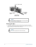
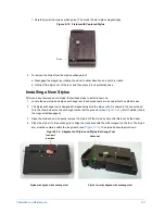
Figure 9-10: Stylus Exchange Tool Details
b.
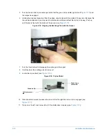
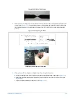
Place the stylus exchange tool underneath the scan head.
c.
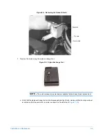
Align the pins of the stylus exchange tool with the stylus sensor housing.
Figure 9-11: Aligning the Stylus Replacement Fixture
d.
Push the stylus exchange tool up until the bottom of the scan head is against the top of it. Be sure the
stylus is seated in the channel on the tool. If necessary, gently tap the end of the stylus shaft (NOT the
tip) with your finger to align the shaft with the channel.
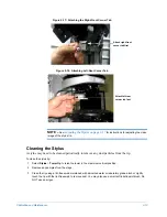
Figure 9-12: Scan Head Flush with Fixture
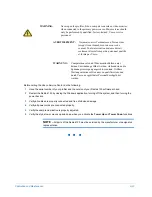
NOTE –
If the stylus is not properly seated in the channel, it will tend to rotate when you
remove it.
e.
Rotate the magnet wheel to engage the magnet (so that the green dot is visible) in the stylus exchange
tool (see the right side of
).
Magnet Disengaged
(Stylus Released)
Magnet
Wheel,
Green Dot
Visible
Magnet
Wheel,
Notch
Visible
Magnet Engaged
(Stylus Captured)
Alignment
Pins
Stylus
Channel
Summary of Contents for Dektak 150
Page 1: ......
Page 7: ......
Page 17: ......
Page 81: ......
Page 105: ......
Page 149: ......
Page 191: ......
Page 251: ......
Page 257: ...A 6 Facilities Specifications Figure A 6 Dektak 150 without Enclosure Side View ...
Page 258: ...Facilities Specifications A 7 Figure A 7 Dektak 150 Dimensions without Enclosure Top View ...
Page 259: ...A 8 Facilities Specifications Figure A 8 Dektak 150 without Enclosure Center of Mass ...
Page 273: ......
Page 283: ......
Page 321: ......
Page 331: ......
Page 333: ......
Page 336: ......
Page 337: ......
Page 349: ......

