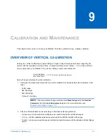
Calibration and Maintenance
9-1
9
C
ALIBRATION
AND
M
AINTENANCE
This chapter tells you how to keep your Dektak 150 surface profiler in top working condition.
OVERVIEW OF VERTICAL CALIBRATION
Setting the vertical calibration requires taking a height or depth measurement and comparing the
results with the standard’s certified value. A measured value that is within
± 0.5%
of the certified
value ensures that your Dektak 150 system is taking accurate measurements.
Here are the general steps for vertical calibration:
1
Determine the measurement range that you want to calibrate first. Ideally, perform the calibrations in this
order:
•
65
kÅ
range
•
655
kÅ range
•
5240
kÅ range
•
Optional 1 mm range
NOTE –
The measurement range is selected in the
Meas Range
list on the
Nominal
Parameters
tab of the
Scan Parameters
dialog box. For more information, see
Measurement Range on page 7-10
.
2
Place a certified standard on a leveled stage. Follow these selection guidelines:
•
A single 5
μ
m (50
kÅ) calibration standard can be used for the 65 kÅ and 655 kÅ ranges.
•
A 10
μ
m (100
kÅ)
calibration standard is preferred for the 655
kÅ
and 5240
kÅ
ranges.
•
The the 1 mm range requires the special vertical standard that comes with the Extended Vertical Range
option.
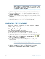
Certified Value
Measured Value
------------------------------------------
VCF Vertical Calibration Factor
(
)
=
Summary of Contents for Dektak 150
Page 1: ......
Page 7: ......
Page 17: ......
Page 81: ......
Page 105: ......
Page 149: ......
Page 191: ......
Page 251: ......
Page 257: ...A 6 Facilities Specifications Figure A 6 Dektak 150 without Enclosure Side View ...
Page 258: ...Facilities Specifications A 7 Figure A 7 Dektak 150 Dimensions without Enclosure Top View ...
Page 259: ...A 8 Facilities Specifications Figure A 8 Dektak 150 without Enclosure Center of Mass ...
Page 273: ......
Page 283: ......
Page 321: ......
Page 331: ......
Page 333: ......
Page 336: ......
Page 337: ......
Page 349: ......

