8-6
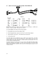
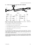
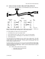
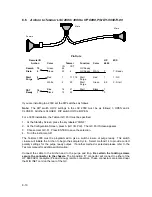
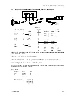
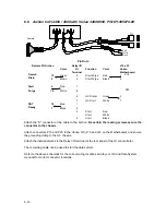
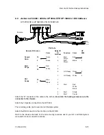
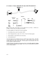
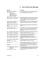
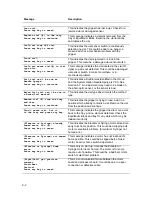
When connecting to a Varian series 3400 or 3600 GC with Star Workstation, connectors from
both the Archon I/O cable and the Star Workstation cable must access the J16 and J23
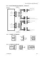
connectors on the GC motherboard. This is possible using the J16 Splitter (DY-700030-00) and
the J23 Splitter (DY-700031-00) following the instructions below:
1) Turn off the power and unplug the power cord from the GC. Remove the top panels
to allow access to the GC motherboard.
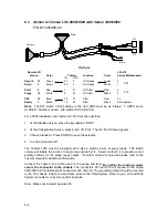
2) Route the GC-end of the Archon I/O cable and the GC-end of the Star Workstation
cable through the back panel of the GC (see Star Workstation installation diagram).
3) Connect the 5-pin female Molex connector (P-23) from the Star Workstation cable to
the male connector on the J-23 Splitter with 4 pins (the #2 position lacks a pin).
4) Connect the 5-pin female Molex connector from the Archon I/O cable to the 5-pin
male connector on the J-23 Splitter.
5) Connect the J-23 Splitter to the J-23 connector on the GC motherboard (see GC
manual for motherboard layout schematic).
6) Connect the 4-pin female Molex connector from the Archon I/O cable to either of the
4-pin male connectors on the J-16 Splitter.
7) Connect the 4-pin female Molex connector (P-16) from the Star Workstation cable to
either of the 4-pin male connectors on the J-16 Splitter.
8) Connect the J-16 Splitter to the J-16 connector on the GC motherboard (see GC
manual for motherboard layout schematic).
9) Complete the installation of the Archon I/O cable and of the Star Workstation cable
according to the standard instructions for those cables.
Technical Note: The following sequence occurs when the Archon and a Purge and Trap unit is
configured with the Varian 3400 and 3600 GC with Star Workstation:
1) The Archon begins its sample handling after receiving a Ready signal from the Purge
and Trap unit. As configured above, the Purge and Trap goes to Ready without
waiting for the GC. This allows the user to prepare the GC or Workstation while the
sample is being purged and collected in the Purge and Trap.
2) The Purge and Trap collects the purged sample onto its trap and waits for a Ready
signal from the GC. This occurs after the Workstation issues a Ready signal to the
GC through the Workstation’s cable plug attached to the GC’s J-16 “Ready-In” pins,
1 and 2. In turn, the GC sends a “Ready-Out” signal from its J-23 pins 1 and 3 into
the Archon I/O cable.
3) When the Purge and Trap has both completed its purge cycle and detected a Ready
signal from the GC, the Purge and Trap desorbs the sample from its trap and issues
a “Desorb-Out” signal to both the Archon and to the Varian GC. This signal travels
through the Remote I/O cable supplied with the Archon.
4) The Desorb-Out signal from the Purge and Trap starts the Archon’s “AutoDrain” cycle
which drains the sparge vessel if a water-sample method is being run on the Archon.
5) The Desorb-Out signal simultaneously travels through the Archon Remote I/O cable
to its connector attached to the GC’s J-16 Start-In pins, 3 and 4, and initiates the GC
run. The GC in turn initiates a “Start-Out” signal through J-23 pins, 4 and 5, which
triggers the Workstation to begin data collection.

