background image

Maintenance

03-914642-00:6

7-7

5.  Trace the valve wires to the rear panel and unplug the connector.  Cut off the

old connector, then remove the valve (15) from its mount.

6.  Install the new valve in the reverse order.  Run the valve wires through the

back panel then attach the connector.  Reinstall the probe, upper soil valve,
and cover.  Reinstall the power cord and turn the power back on.

Note:

In Figure 7-3 when removing Angar valve you must remove metal plate
under mount plate (13).  Remove insulated divider then remove three
socket head screws on top of mount plate.

7.10 

Sample Stir Motor Speed Adjustment

The speed of the sample stir motor may be increased or decreased by the
adjustment of a pot. A small jeweler's screwdriver (1/16" flat blade or Phillips) is
required.

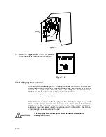
1.  Locate the pot access hole, on the rear panel of the Archon on the upper left

side. The hole is below the 9-pin “D” connector labeled “Remote RS-232.”

2.  Start a manual sample. Be certain the stir motor is turned “ON” in the

method.

3.  Insert the screwdriver into the hole and rotate the pot, CW will increase the

speed and CCW will decrease the speed. Observe the response on the stir
motor magnet.

C A U T IO N

Only slight pressure is necessary. Do not push hard
with the screwdriver as damage may occur.

4.  Once the speed is adjusted, stop the run.

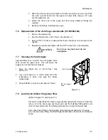
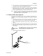
Figure 7-5

Stir Motor
Adjustment Hole

Summary of Contents for archon

Page 1: ...Varian Analytical Instruments 2700 Mitchell Drive Walnut Creek CA94598 1675 USA Varian Inc 1999 Printed in U S A 03 914642 00 6 Purge and Trap AutoSampler System Operator s Manual ...

Page 2: ... 2 2 2 5 Gas Connections 2 3 2 6 Electrical Connections 2 4 2 7 Electronic I O Signal Connections 2 4 2 7 1 Purge and Trap Sync Cable Connector 2 4 2 7 2 Personal Computer Connection 2 4 2 8 Water and Waste Lines Setup 2 4 2 8 1 Blank Wash Bottle Setup 2 4 2 8 2 Waste Lines Setup 2 6 2 9 Sample Tray Setup 2 6 2 10 Sample Tray Coolant Setup Optional 2 7 2 11 Archon Soil Transfer Line Installation 2...

Page 3: ...ing 5 5 5 4 Method Programming Guidelines 5 6 5 4 1 Water Method Program 5 6 5 4 2 Soil Method Program 5 6 5 4 3 Blank Method Program 5 7 5 5 Equilibrium Count and Equilibrium Time 5 7 5 6 Operating Sequence Steps 5 8 5 6 1 Water Sample Sequence 5 8 5 6 2 Soil Sample Sequence 5 10 5 6 3 Blank Sample Sequence 5 11 6 System Setup 6 1 6 1 Front Park 6 1 6 2 System Status 6 1 6 3 Maintenance 6 2 6 3 1...

Page 4: ...ing 7 8 7 12 Cleaning or Replacing the Syringe Plunger O ring 7 8 7 13 Cleaning the Internal Standard Valve and Lines 7 10 7 14 Installation of the Internal Standard Vials 7 11 7 15 Shipping Instructions 7 12 8 Remote I O Cable Hookup Instructions 8 1 8 1 Archon to Tekmar LSC 2000 and 3000 P N DY 505872 00 8 2 8 2 Archon to Tekmar 3000 with HP 5890 P N DY 505869 00 8 3 8 3 Archon to Tekmar LSC 200...

Page 5: ...1 11 2 Syringe Plate 11 2 11 2 1 Internal Standard Valve Assembly 11 3 11 2 2 Mixing Solenoids 26 mL Syringe Assembly 11 4 11 2 3 Probe Section 11 5 11 2 4 Vial Sample Stations 11 6 11 3 Interface Transfer Line Purge Gas Solenoid 11 7 11 4 Rear Panel 11 8 11 5 Robotic Arm 11 9 11 6 Interconnect Diagram 11 10 12 Flow Diagrams 12 1 ...

Page 6: ...arm transfers the vial to the vial identification step and then lifts the vial into the heated chamber where water is added with one or both standards the sample is then purged directly onto the trap of the concentrator If a water sample is to be run the sample is placed in a 40 mL VOC vial and a stir bar optional is placed in the vial and the vial is placed in the tray The Archon robotic arm move...

Page 7: ...als Optional sample tray cooling capability Optional refrigerated chiller is required Priority Sample feature allows the current analysis to be interrupted for RUSH samples Easily readable back lit LCD display Fast easy programming from the touchpad keyboard 30 programmable methods may be stored for various method configurations A sample may be run from any position in the tray Easy hook up and in...

Page 8: ...lation Category II Pollution Degree 2 Heat Dissipation 2500 BTU Hr Max Worst Case Weight Approximately 80 lbs 36 5 Kilograms Size 21 5W x 17H x 20D inches 54 6W x 43 2H x 53 3D centimeters Gas Requirements Helium 60 90 PSI 99 999 GC MS grade purity 1 4 Component Description The Archon consists of a base unit with a 51 position sample tray The sample tray is removable from the front A description o...

Page 9: ...rovided to attach to a waste bottle or a sink drain Remote I O All communication to the purge and trap and GC are made via the 25 pin D connector Custom built cables are designed for each purge and trap system to ensure correct handshaking Remote RS 232 A 9 pin RS 232 D Connector will allow for operation via a computer with a Windows compatible program Water Connections A water input connection is...

Page 10: ...probe is rinsed in a chamber that prevents sample from spraying onto the instrument components 3 Soil Probe The patented soil probe and the Needle Sparge probes incorporate a T fitting design for attachment of water and heated transfer line The probe is installed in a heated oven and easily removable for cleaning or replacement 4 26 mL Syringe A 26 mL syringe is used to move sample blank flush and...

Page 11: ...e of the Archon and slide the 1 4 ID hose over the fitting Route the other end to a drain 1 5 Vial Types The Archon may use two different types of sample vials depending on the sampling type option installed The two types of vials are shown below Patented SoilVial This vial is used if the Archon is purchased with the SoilVial Option installed This double ended vial contains a frit at the bottom en...

Page 12: ...rtons Lifting from the bottom remove the Archon from its carton the largest box Place it on the bench to the left side of the concentrator Remove the sample tray interface kit interface cable and any accessory or spare items from the second carton Inspect for possible shipping damage or shortages If damage is discovered immediately notify the carrier and Varian Varian Analytical Instruments 2700 M...

Page 13: ...el flange free ferrule 1 16 6 x 15 mm stir bars pkg of 6 1 ea 80 oz safety coated bottle 22 mm low bleed septa pkg of 60 EPA 40 ml water vials and caps pkg of 12 51 position sample tray note this is shipped in a separate box Composite warning labels Water Transfer Line SS 1 16 x 5 long Stir bars soil pkg of 6 supplied with SoilVial version only 2 ea SoilVial supplied with the SoilVial version only...

Page 14: ...Helium Input Gas line must be 1 8 diameter copper tubing and fittings must be 1 8 Swagelok Use a single two stage high quality pressure regulator with a stainless steel diaphragm Consult your supplier for the proper type and size of cylinder valves An on off shut off valve should be installed in the line to facilitate installation Gas line tubing should be generous Allow enough length in a coil to...

Page 15: ... high TTL logic others use normally open contact closures or active low TTL logic Refer to the operator s manual for each system for signal information The Archon signal input configuration must be established to properly receive the purge and trap s output signals for Standby Desorb and Stop System Settings details the parameter configurations for each of the signals The factory default setting f...

Page 16: ...ce Turn the toggle valve for blank water reservoir and standard helium to the ON position The valve is located inside the cabinet on the right rear wall see Figure 2 3 To test for a pressurized bottle depress the vent button located on the blank waste bottle plug You should hear the release of pressure To refill the bottle turn the toggle switch OFF and vent the bottle by depressing the chrome but...

Page 17: ...s shipping carton The tray is installed in the Archon behind the lower door Notice the tray has 51 positions and each location is numbered Raise the large tray cover and secure the arm lock by gently pushing it in the center and then lowering the cover Press the latch button on the top edge of the lower door and pull the door down Grasp the handles on the tray and insert the tray into the Archon w...

Page 18: ... that can be attached to the coolant coil It is located inside the cabinet under the tray The tray rests on top of the coil allowing conductive transfer of temperatures See Figure 2 4 The coolant connections are located on the rear panel at the lower right corner and are labeled Tray Coolant IN OUT The tubing is 3 8 Duro Refer to the instructions included with the coolant and plumbing installation...

Page 19: ... items are correct Refer to Sections 2 1 through 2 3 for unpacking and component details The installation of the Archon will require the use of two different types of nuts and ferrules See Figure 2 5 Figure 2 5 2 11 1 Archon to Tekmar 3000 WARNING SHOCK HAZARD Dangerous voltages exposed when covers are removed Unplug power cord Note The Tekmar 3000 valve oven may be configured with one of two diff...

Page 20: ...three port fitting to the cabinet 3 Using a 1 4 open end wrench loosen the nuts in all three ports 4 Loosen the two screws which secure the sparge tube mount to the cabinet 5 Pull the sparge tube mount and tubing out of the 3 port fitting and off the instrument 6 Pull each of the other two lines out 7 Replace the original fitting with the new 4 port cross fitting 8 Attach all of the lines into the...

Page 21: ...1 01 02 Bolt with spacer Transfer Line Sheath Clamp with Standoff for GC Transfer Line Only GC Transfer Line Six Port Valve Archon E Form Nickel transfer Line DY 505745 00 Four Port Cross Fitting DY 505716 00 Sparge Tube Sparge Tube Mount Oven Thermocouple Clamp ...

Page 22: ...on line assembly into the Tekmar 3000 transfer line channel The Archon line will rest on the top of the Tekmar 3000 GC transfer line 3 Bend the end of the Archon nickel transfer line so it will fit into the open port on the 4 port cross fitting Using a 1 4 open end wrench tighten the nut See Figure 2 6 Be careful not to kink the line 4 Push the two lines down into the channel Installation of the H...

Page 23: ...gh the notch in the rear panel of the Archon labeled waste lines Figure 2 9 Water Transfer Line Installation The Archon transfers cleans and dilutes liquid samples to the sparge tube via a five foot stainless steel line and attaches to the 2 way valve on the top of the sparge tube Refer to Figure 2 9 Soil Transfer Line Cap Screw cover removed Upper Soil Valve Tekmar Heated GC Transfer Line Assembl...

Page 24: ...e left side of the toggle valve Tighten the nut 7 Replace the rear door panel 8 Remove sparge vessel Make a slight bend about 3 7 2 cm from end of needle This maximizes the rinse ability of the Archon Note Make sure needle is not touching frit Tekmar 3000 Setup Specifications After the Archon is installed the Tekmar 3000 MUST be properly configured for the I O switch closures and method parameters...

Page 25: ...ple Status C Commands E Edit Schedule Select C A Run Schedule B Update Schedule C Clear Schedule Select A This will load New method To verify look in the upper right hand corner of the key pad Display M and the new method selected should be displayed 2 11 2 Archon to Tekmar 2000 WARNING SHOCK HAZARD Verify that both the Archon and the Tekmar 2000 are turned OFF and the power cords are disconnected...

Page 26: ... of the 2000 through the hole labeled ALS Attach the line to the bottom left port on the new fitting 5 Attach the line from the Dry Purge valve previously removed from the 2000 tee to the top right port of the new fitting 6 Check all fittings to ensure they are tight Figure 2 10 Installation of the Heated Soil Transfer Line 1 Inside the Archon use an Allen wrench to loosen the screw securing the p...

Page 27: ...onnect the red PEEK tube to the sparge tube fitting Use 1 16 nut and ferrules for this connection Refer to Figure 2 13 4 Route the peek tubing lines through the notch in the rear panel of the Archon labeled waste lines Figure 2 13 Soil Transfer Line Cap Screw cover removed Upper Soil Valve Hole Archon Heated Transfer Line Bracket GC Transfer Line Archon Water Transfer Line 2 way Sample Valve Blue ...

Page 28: ...ge tube 5 Turn the handle so the valve is open toward the Archon transfer line Look in the port to ensure the holes are aligned 6 Slide the nut and reverse ferrule over the line and insert into the port on the left side of the toggle valve Tighten the nut 7 Replace the rear door panel 8 Remove sparge vessel Make a slight bend about 3 7 5 cm of needle This maximizes the rinse ability of the Archon ...

Page 29: ...s Attach the clamps with line to the bracket using the 6 32 x 1 2 screws with nuts and lock washers 3 Slide the special fitting P N DY 505727 00 provided in the Installation Kit onto the transfer line Carefully bend the line and insert it with the fitting into the AS port on the OI 4560 With a 5 16 wrench tighten the larger nut first Push the line into the fitting and tighten the 1 4 nut 4 Check a...

Page 30: ...of soil transfer line to O I 4560 Clamp Heated Transfer Line Assembly Water transfer Line From Archon red PEEK tube VOC Transfer Line Purge Gas Outlet Blue PEEK tube connects here Sparge Tube Fitting Special 4560 Fitting Compression Nut on Sample Valve for Water Transfer Line ...

Page 31: ...2 Insert the free end of the transfer line into the rear of the Archon the line will pass the open slot Attach the transfer line bracket to the panel with the two 4 socket head screws already installed in the rear panel 3 Attach the transfer line to the upper soil valve using a 1 4 open end wrench 4 Reinstall the insulation block and the probe cover and screw Figure 2 15 Cap Screw cover removed Up...

Page 32: ... line will attach to the black 2 way valve on the top of the sparge tube 5 Rotate the two way valve above the sparge tube so the ports are facing left and front The Luer fitting should be to the front Remove the drain line Using a 5 16 wrench install the modified Swagelok union with rubber washer to the port on the left side Route the line around the left side of the purge and trap to the sample v...

Page 33: ...cond Config Bake Sample Purge ON then ENTER 7 Press the Clear key to exit 2 12 Soil Helium Purge Gas Flow Adjustment Before running a soil sample the helium purge gas flow rate should be set This is accomplished by the helium purge gas flow controller 1 pressure adjustment regulator 2 and gauge 3 located on the front right side of the Archon see Figure 2 17 1 Adjust the purge gas regulator until t...

Page 34: ...binet Confirm the supply helium pressure is between 70 90 PSI 5 PSI Be certain the handle on the black sample valve located on top of the sparge vessel is rotated in the position of the water transfer line Do not overtighten the cap on the blank wash bottle To properly tighten the cap turn it until snug then stop Be certain the septum used for the soil samples is P N DY 504104 00 It is extremely i...

Page 35: ...ttings The vial MUST move freely in and out of the tray without resistance Refer to Section 6 4 Permanant marker pens are recommended to label sample vials Otherwise no more than two labels should be applied to the vials The waste bottle or drain MUST be placed at a location which is equal to or lower than the base of the Archon Make sure the sample needle in the sprage tube does not sit centered ...

Page 36: ...ational Setup and Special See Section 4 Operation Keys for a complete description of operational key functions Numeric keys are used to enter numeric values 0 9 for entering numeric information such as time or temperature programming Operational Keys Auto Starts the autosampling procedure see Section 4 1 Manual Starts a single sampling procedure or runs a Priority Sample see Section 4 2 Flush Perf...

Page 37: ...etting Also used to toggle the current motor selection and place the Archon in SYSTEM HOLD Acts as a backspace key Allows erasure of the current value of any data entry item 4 6 8 2 These keys have dual functions They are numeric as well as directional keys These keys are used to scroll up or down for menu selection and operation of motors in System Calibration This is an Escape Key It can be used...

Page 38: ...egin To start the Archon at a later time use the DELAYED START feature Using the 2 key scroll down to the DELAYED START command line Press ENTER The screen will now display a menu line Delay xx xx hours Use the numeric keypad to enter the amount of time delay before starting the AutoSampler sequence Note The time entered will be in hours and hundredths of an hour Once the value is entered press EN...

Page 39: ... the Archon will not identify a vial type automatically Using the numeric keypad enter the Method number containing the correct Sample Blank parameters press ENTER The Sample Type will be updated to the method s sample type If no change is made the method number defaults to the last one used The Sample Type Soil Water or Blank may be displayed depending on the last sample type run The sample type ...

Page 40: ...he ENTER key may be pressed to resume the AutoRun To cancel out of the Priority Sample menu press the Manual key again 4 3 Flush Key The system is automatically flushed between samples However you may want to manually flush the system if contamination or carryover occurs The Flush Key offers four options to decontaminate the water and soil sample pathways 1 Drain the sparge tube 2 Flush the 26 ml ...

Page 41: ...elections Keypad Display Entry Range Flush Syringe Flush Times xx Flush Volume xx Flush Syringe 1 20 1 25 Using the numeric keypad enter the desired number of flushes from 1 20 Press ENTER scrolling to the next menu line Flush Volume Enter a value from 1 25 ml Press ENTER key scrolling to the next menu line Flush Syringe Press ENTER again to initiate the Flush Syringe sequence Note this Flush sequ...

Page 42: ...indicating the Pause Stop has been pressed Once the sample run is complete the S is removed then the following message appears on the screen The Manual Flush Method and System keys are now functional Methods may be edited Manual Sample may be performed or any of the System parameters can be changed Press ENTER to resume the AutoRun from the point it was paused Pressing the key twice will cause an ...

Page 43: ...4 6 ...

Page 44: ...lid entry is made the system will change the value to be within the allowable range To exit Method Parameters press the Method key again Any changes will be automatically saved Methods can be built for water soil or blank samples using the following procedures Although all parameters are listed below only certain ones apply to each method type Recommended parameters for blank water and soil sample...

Page 45: ...ether to the volume of 24 3 mls DF NO is no dilution DF 2 is 1 volume sample blended with 1 volume blank water 50 dilution DF 50 is 1 volume sample blended with 49 volumes blank water 98 dilution The 4 key is used to change the dilution factor Rinse Volume 0 25 ml 05 Volume of rinse water used to flush the PAT sparge tube during the bake mode The volume may be set in 1 ml increments Rinses 0 20 01...

Page 46: ...syringe and out to waste PreHeat YES NO YES This parameter will allow the sample to heat prior to purging The heating will occur after the water is added Note This is a soil method only setting PreHeat Temp amb 140 C 40 C This parameter sets the temp for the preheating of the sample Note This is a soil method only setting PreHeat Time 0 99 9 min 3 0 min This parameter sets the time for preheating ...

Page 47: ...e ready signal is received from the purge and trap in the standby mode The cycle includes the purge time plus the GC run time and cool down The cycle time is normally used to ensure that the GC will be ready to receive the next sample In the case of short GC run times cycle time will not be effective and should be set to 0 Auxiliary Timer 0 99 9 min 00 0 min This is a timed event output used to st...

Page 48: ...u Then press the Method key to exit to the METHOD menu Scroll down to Edit Blank Vials and press Enter The Method Blanks menu as shown will allow the programming of a single blank water run after any of the sample vials in the method Note that the vial numbers for which a following blank may be programmed are restricted to the range defined by the First Vial and Last Vial entries in the earlier me...

Page 49: ... Link to Method Water 1 5 5 ml 0 5ml 2 YES NO NO 0 0 1 4 MIN Remote 65 min 0 2 5 4 2 Soil Method Program The following is an example of a typical soil method that can aid building your method You may start with these settings then make adjustments as necessary after running several standards and or samples In this example Method 2 will be programmed for Soil Note If a recirculating bath is install...

Page 50: ...ess of method the Equilibrium Time parameters are actually set within the system settings menus see Section 6 6 They are discussed here for continuity The Equilibrium Count is the number of vials 5 is the maximum to be placed in the Equilibrium zone station for temperature equilibrating see Figure 5 1 Initially the vials are loaded in the zone starting with the left vial identification section eac...

Page 51: ...lows particulates to settle 7 Elevator up The sample vial is raised onto the water probe 8 ml for backflush 9 No sample dilution Programmed dilutions are performed 10 ml for backflush 11 Helium waste Helium flushes sample path to waste bottle 12 Water waste Water flushes sample path to waste bottle 13 Helium waste Helium again flushes sample path to waste bottle 14 Adding standard 1 and or 2 Stand...

Page 52: ...er the water backflush is complete the probe is now flushed with helium 31 Elevator down The elevator moves down 32 Autodrain The Archon waste valve opens and helium pressure from the purge and trap will now drain the sparge tube 33 Drain sparge tube The Archon will initiate a safety drain 34 Sparge tube syringe If any sample water remains in the sparge tube it is drawn into the syringe 35 Syringe...

Page 53: ...p The sample vial is now raised up onto the soil probe 7 Syringe fills Syringe fills with programmed amount of water 8 Adding standard 1 and or 2 Standard 1 and or 2 is added to the sample 9 Water soil vial Water is transformed to the soil vial 10 Helium waste Helium flushes sample path to the waste bottle 11 Pre heat Soil Sample Sample vial is heated 12 Pre heat Time Length of time of heating 13 ...

Page 54: ...ough the sample path to the waste bottle 27 End soil sample This completes the soil sample process sequence 5 6 3 Blank Sample Sequence Sequence Step Purpose 1 Water lines Water flushes internal standard path to the waste bottle 2 Water syringe Water is now transferred to the syringe 3 Helium lines Helium flushes sample path to the waste bottle 4 Adding standard 1 and or 2 Standard 1 and or 2 is a...

Page 55: ...e waste bottle 17 Sparge tube syringe If any sample remains in sparge tube it is drawn into syringe 18 Syringe waste The syringe transfers sample to the waste bottle 19 Helium waste Helium is again flushed through the sample path to the waste bottle 20 Flush syringe If flushes have been programmed 21 Heating water Water is heated 22 Water lines Hot water now fills the lines 23 Water syringe Hot wa...

Page 56: ...easy access to the rear of the Archon for service or maintenance Using the 2 or 8 keys select the Front Park menu line press ENTER The display will now show Press any key to rear park gripper Press any key to begin moving the Robotic Arm The System Setup menu will be displayed during the movement Once stopped the rear park screen will be displayed Press any key to front park gripper After the serv...

Page 57: ...ed with standard This menu also allows the user to reset movement counters System Maintenance Standard Control Adjust Counters Shipping position Clean Syringe Elevator up down test 6 3 1 Standard Control Select from the main menu Standard Control press ENTER The Standard Control menu will be displayed Select the Front Park command Press ENTER The Robotic Arm will now move to the front left corner ...

Page 58: ... ml syringe plunger each time it reaches its home up position Waste Block this is a count of the movement of the water probe into the Waste Block During the clean up cycle the tip of the water probe is covered and the entire probe is flushed with water and helium Select the Adjust Counters menu line press ENTER The Counter menu will be displayed The numeric key pad is used to change the count data...

Page 59: ...on for specific instrument operations Note Once a calibration step is initiated all of the above steps must be performed to assure the unit is properly aligned The Calibration Test and Auto Calibrate routines allow automated testing and readjustment of most of the robotic arm calibration settings These routines are used to quickly verify the operational status of the robotic arm and to make adjust...

Page 60: ...Calibration Bar P N DY 505894 00 and Calibration Pin P N DY 505893 00 shipped with your instrument Note To order a replacement Calibration Bar and Calibration Pin order Kit Number DY 505419 90 To run the Auto Calibrate program press the System key from the key pad The System Setup menu will be displayed Using the 2 or 8 key scroll to the Calibration menu line and press ENTER Scroll up one position...

Page 61: ...e and run the program again Once the Auto Calibration is complete place a 40 mL VOA in Position 22 Scroll down using the 2 key to vial 22 position and calibrate the vertical height Press the 7 key for Train Press 7 key for train again compare first and second calibration numbers If the numbers stay within 5 6 digits complete water probe and equilibrium block using the 7 key to train After completi...

Page 62: ...de pressing a motion key commands a movement of one step The step size is described below In Jog mode the axis motor runs continuously as long as the motion key is pressed Jog is used for long fast movements 5 Step Size Allows editing of the step size for motion in the Step mode The step size is relative to the number of pulses sent to the axis motor More pulses gives longer steps resulting in gre...

Page 63: ...routine The arm will return to its home position 6 4 4 Water Probe Vial Position This coordinate setting positions a 40 ml water sample vial into the water vial cup insuring the probe will penetrate the vial properly see Figure 6 2 Figure 6 2 Use the following procedure to recalibrate this position 1 Place a capped full vial in sample tray position 22 2 From the Calibration Setup menu scroll to th...

Page 64: ...ic Arm will move and the following message will be displayed Equilibrium Block Press Enter to get vial 22 for Alignment or any other key to skip 4 Press ENTER The arm will retrieve the vial go to the equilibrium block area and a version of the Coordinate Settings menu as described in Section 6 4 8 will be displayed on the screen 5 Press 7 to train the gripper s vertical height for grasping vials 6...

Page 65: ...y either 8 or 2 to adjust the clearance If the gripper steps too far adjust the step size by pressing 5 8 Press ENTER to save the position values and complete the routine The arm will return to its home position 6 4 7 Standard Clearance This coordinate setting establishes the correct clearance for the gripper arm to pass under the glass standard vials when accessing the vial identification positio...

Page 66: ...y other means Note that the original positional settings determined at the factory during the instrument s manufacture are recorded on the reference sheet attached to the inside of the Archon right chassis panel In certain instances it may be useful to directly re enter these original values through the Manual Calibration menu items When a manual calibration routine is chosen from the Calibration ...

Page 67: ...eft right Motor Front rear Motor Up Down Motor Probes U D Motor Gripper Solenoid Remote Inputs Remote Outputs Select the desired menu line with the 2 or 8 key Press ENTER Once selected the screen will display the function Left Right Motor etc If the function is for a Motor or the Gripper Solenoid the following message will be displayed Function Left Right Motor to be tested Press Enter to test Any...

Page 68: ...lows the relay Output signals to be tested The line U D scrolls through the relay signals Use the 2 or 8 keys to scroll The L R line changes the status of the relay Output from keep open to closed pulse Use the 4 or 6 keys to scroll The ENTER key is used to pulse the signal for test purposes Injection Mark Aux Output Soil Vial Start Purge The Output signals are Injection Mark This is a test of the...

Page 69: ... Soil Probe Temperature This is the temperature setting for the Soil VOC upper probe Note A temperature setting of 0 will turn the heater OFF XFER Line Temp Transfer Line Temperature This is the temperature setting for the VOC transfer line to the purge and trap Note A temperature setting of 0 will turn the heater OFF Upper Soil Valve Temp Upper Soil Valve Temperature This is the temperature setti...

Page 70: ...ample will remain in the Equilibrium section to reach ambient temperature The 2 and 8 keys will step the brackets to the next menu line The numeric keypad is used to change numeric value settings the 4 and 6 keys are used to toggle from Open to Closed on signal polarity settings The ENTER key will accept the value and toggle to the next line Default Operation Value Table Parameter Factory Default ...

Page 71: ...le vials in the Barcode Scanner Zone prior to vial type detection The barcode label on the vial will be read and the information may be retrieved to a PC for its use Only one barcode label will be retained for each vial position Needle Sparge If the Archon is setup for Needle Sparge sampling this option must be YES The sample vial type sensor will then be reversed to detect water 40 ml VOC vials I...

Page 72: ...r prior to entering the 25 ml syringe and sample transfer lines Vial Checks This option will cause the Robotic Arm to search the equilibrium and vial sampling locations for vials during start up The Archon will remove the vials and return them to the sample tray CAUTION This option should be set to YES to prevent vial jams Beep on Error This option causes the Archon to produce an audible Beep when...

Page 73: ...6 18 ...

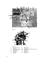
Page 74: ... power cord Allow sufficient time for all heated zones to cool before proceeding When cleaning any components of the Archon e g exterior robotic slide rods or leadscrews gripper arms or sample tray use only an isopropanol and water solution placed on a lint free and oil free cloth 7 1 Removal and Replacement of the Needle Sparge or SoilVial Probe WARNING BURN HAZARD The cover and probe are hot Ref...

Page 75: ...d nut 3 Sample out line short line 11 Reverse ferrule Super Flangeless nut ferrule 4 soil transfer line and nut 12 Retaining nut 5 Helium flush line 13 Mount plate 6 4 40 Screws 14 Valve manifold 7 Probe retainer 15 Upper soil valve 8 Probe body 16 Short line 2 15 4 3 6 10 12 14 11 5 7 6 13 9 16 8 ...

Page 76: ...er forward tighten the two 4 40 screws 6 3 Attach the sample out line 3 and the helium flush line 5 4 Attach the 5 16 nut 2 to the bulkhead fitting for the helium purge water supply line 5 Be certain all fittings are tight snug and 1 4 turn 6 Replace the cover 7 2 Removal and Replacement of the Water Probe Refer to Figure 7 2 and Figure 7 3 Removal 1 With a 5 16 wrench loosen and remove the brass ...

Page 77: ... and pull the screen out 3 Insert the screen into the hole the white side of the screen faces out 4 Insert the flangeless fitting and ferrule 11 into the hole in the manifold 14 Finger tighten the nut 7 5 Replacement of the Soil Transfer Line Nickel Line Only DY 505745 00 See Figure 7 2 and Figure 7 3 Removal 1 Remove the upper soil valve cover shown in Figure 7 1 Referring to Figure 7 2 and Figur...

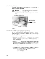
Page 78: ...7 Cleaning the Vial Gripper Approximately once a month the vial gripper arms 17 should be wiped clean This will insure the gripper s arms hold the vial properly 1 Move the robotic arm to Front Park See Section 6 1 2 Use a soft tissue or a cotton swab with 30 isopropanol in water and wipe the rubber gripper pads 3 Press ENTER to move the arm back to Home Vial G ripper 16 Figure 7 4 7 8 Leak Check H...

Page 79: ...il valve is leaking and it should be replaced 5 If the flows do match the fitting on the end of the soil transfer line in the purge and trap may be leaking or a leak exists within the purge and trap 6 Reattach the transfer line into the upper soil valve and recheck the flow at the host purge and trap vent If the flows do not match check the fitting on the soil transfer line in the purge and trap a...

Page 80: ...Sample Stir Motor Speed Adjustment The speed of the sample stir motor may be increased or decreased by the adjustment of a pot A small jeweler s screwdriver 1 16 flat blade or Phillips is required 1 Locate the pot access hole on the rear panel of the Archon on the upper left side The hole is below the 9 pin D connector labeled Remote RS 232 2 Start a manual sample Be certain the stir motor is turn...

Page 81: ... 7 7 1 Turn the helium flow Toggle Switch OFF 2 Start from the main Archon menu Press the System key Using the 2 or 8 key scroll through the menu selections until the Maintenance line is selected Press ENTER 3 Using the 2 or 8 key again scroll through the menu until the Clean Syringe line is selected Press ENTER the gripper will move to the front and the following menu will be displayed Follow the...

Page 82: ...ement remove the old o ring from the plunger Warm the new o ring in very hot water for several minutes The new o ring will slide on the plunger from the rear With ONLY your fingers gently push the o ring into the plunger s groove Do not scratch the o ring with your fingernails NEVER use a tool Note Make sure the barrel and plunger are free of any buildup 9 Wet the top end of the 26 ml syringe glas...

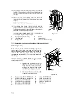
Page 83: ...leaning the Internal Standard Valve and Lines Refer to Figure 7 8 If the recovery of the internal standard s appears to be too low or is erratic the lines to and from the internal standard valve and the valve rotor should be cleaned The following steps detail the cleaning maintenance procedure A 1 4 open end wrench is necessary Turn the helium gas OFF with the toggle switch refer to Figure 7 10 1 ...

Page 84: ...Insert the rotor into the valve BE SURE THE GROOVE IS FACING DOWN Install the knurled knob Using your fingers tighten the knob until it will no longer rotate 10 Turn the helium toggle switch to ON Note If it is necessary to remove the 5 ml standard reservoir vials be very certain the helium toggle switch is off Grasp the vial before rotating the black thumbnut 11 7 14 Installation of the Internal ...

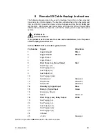
Page 85: ... Maintenance menu line Shipping Positions Press ENTER the display will now show Shipping Positions then Remove tray Remove Power The robotic arm will move to the shipping location the 26 ml syringe plunger will lower and the sample elevator will be raised Once all movement has ceased turn the power off unplug the power cord remove the sample tray and install the shipping screw and spacer through t...

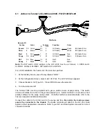
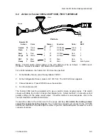
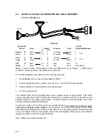
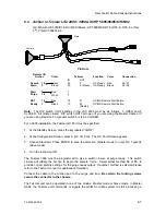
Page 86: ...e installations turn the power off and unplug the instrument Archon REMOTE I O connector signal pin outs Pin Number Signal Wire Color 1 Logic Ground Black 2 Logic Ground Brown 3 Logic Ground 4 Logic Ground 5 Start Purge no Relay Output Red 6 Start Purge nc 7 Soil Purging com 8 Aux Output no 9 Aux Output nc 10 Soil Purging2 com 11 Serial Output Reserved 12 Serial Clock Reserved 13 Serial Load Reser...

Page 87: ...the key labeled CONF 2 At the Configuration Screen press A GC I O Port The GC Port Screen appears 3 Choose Standard GCType 63 Press ENTER to save the selection 4 Turn the instrument off The Tekmar 3000 must be programmed to give a switch closure at purge ready This switch closure will initiate the Archon to begin the sample Cycle Select method 14 to provide correct polarity settings for the purge ...

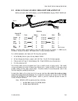
Page 88: ...andby Screen press the key labeled CONF 2 At the Configuration Screen press A GC I O Port The GC Port Screen appears 3 Choose Standard Press ENTER to save the selection 4 Turn the instrument off The Tekmar 3000 must be programmed to give a switch closure at purge ready This switch closure will initiate the Archon to begin the sample Cycle Select method 14 to provide correct polarity settings for t...

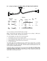
Page 89: ...s A GC I O Port The GC Port Screen appears 3 Choose Standard Press ENTER to save the selection 4 Turn the instrument off The Tekmar 3000 must be programmed to give a switch closure at purge ready This switch closure will initiate the Archon to begin the sample Cycle Select method 14 to provide correct polarity settings for the purge ready output If another method is selected please refer to the Te...

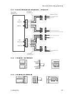
Page 90: ...Remote I O Cable Hookup Instructions 03 914642 00 6 8 5 8 3 1 Varian GC Motherboard Attachments J16 and J32 8 3 2 J 16 Splitter DY 700030 00 8 3 3 J 23 Splitter DY 700031 00 ...

Page 91: ... of the Star Workstation cable according to the standard instructions for those cables Technical Note The following sequence occurs when the Archon and a Purge and Trap unit is configured with the Varian 3400 and 3600 GC with Star Workstation 1 The Archon begins its sample handling after receiving a Ready signal from the Purge and Trap unit As configured above the Purge and Trap goes to Ready with...

Page 92: ...0 installation the Tekmar GC Port must be specified 1 At the Standby Screen press the key labeled CONF 2 At the Configuration Screen press A GC I O Port The GC Port Screen appears 3 Choose Standard Press ENTER to save the selection Master mode or user GC Type 32 slave mode 4 Turn the instrument off The Tekmar 3000 must be programmed to give a switch closure at purge ready This switch closure will ...

Page 93: ...mode be certain the GC MS is ready when the start signal is given Connections Master Cable 1 Locate the remote start button on the GC MS 2 Locate the Master cable Note drawing 3 Connect the Master cable to the receptacle on the rear of the remote start button Slave Cable 1 Locate the Molex plug labeled Accessory Connection on the rear of the GC MS 2 Remove the Molex plug from the remote start butt...

Page 94: ...ss the key labeled CONF 2 At the Configuration Screen press A GC I O Port The GC Port Screen appears 3 Choose User GC Type 31 Handshaking ON Press ENTER to save the selection 4 Turn the instrument off The Tekmar 3000 must be programmed to give a switch closure at purge ready This switch closure will initiate the Archon to begin the sample Cycle Select method 14 to provide correct polarity settings...

Page 95: ...y Screen press the key labeled CONF 2 At the Configuration Screen press A GC I O Port The GC Port Screen appears 3 Choose User GC 31 Press ENTER to save the selection 4 Turn the instrument off The Tekmar 3000 must be programmed to give a switch closure at purge ready This switch closure will initiate the Archon to begin the sample Cycle Select method 14 to provide correct polarity settings for the...

Page 96: ...Start White Data 4 Start Black System Attach the D connector of the cable to the Archon Be certain the locking screws secure the connector to the chassis Attach the 12 position connector to the HP 5890 Attach the individual wires to the Relay I O terminal at the rear panel of the OI concentrator The remaining cable can be used to start the data system Refer to the above schematic for the correct w...

Page 97: ... Red Start White 4 Start Black Attach the D connector of the cable to the Archon Be certain the locking screws secure the connector to the chassis Attach connectors P16 and P23 to the Varian GC J16 and J23 on the Motherboard and secure the grounding clamp to the GC chassis Attach the individual wires to the Relay I O terminal at the rear panel of the OI concentrator The remaining cable can be used...

Page 98: ... 18 White 8 6 GC Ready Green 6 7 GC Ready White 5 14 Blue 1 P T Ready 1 Black 2 5 Start Red White 4 Black 4 Start Shield 5 Start Center Attach the D connector of the cable to the Archon Be certain the locking screws secure the connector to the chassis Attach the 12 position connector to the HP 5890 The remaining cable can be used to start the data system Attach the BNC connector to the start box o...

Page 99: ...een press the key labeled CONF 2 At the Configuration Screen press A GC I O Port The GC Port Screen appears 3 Choose Standard Press ENTER to save the selection 4 Turn the instrument off The Tekmar 3000 must be programmed to give a switch closure at purge ready This switch closure will initiate the Archon to begin the sample Cycle Select method 14 to provide correct polarity settings for the purge ...

Page 100: ...ould be damaged or the vertical coordinate setting could be incorrect See Section 6 Can t Front Park while running Press any key to continue This message displays if the Front Park command is attempted while the instrument is running Can t calibrate while running Press any key to continue This message displays if Calibration Setup was attempted while the instrument is running Can t diagnose while ...

Page 101: ...il method This indicates the vial type doesn t match the method type Remove vial from the tray and then Press any key to continue This indicates the gripper is trying to load a vial in a position which already contains a vial Remove the vial from the position and continue Didn t sense vial Put it in the tray and press any key This message indicates the gripper tried to move a vial back to the tray...

Page 102: ...key to reset This is an internal board communication failure Standard home error Press any key to reset This message indicates the Standard motor has not reached its home position Check for a motor failure or mechanical jam or sensor failure Stack overflow Press any key to reset This is an internal error Contact Varian Subroutine not found Press any key to reset This is an internal error Contact V...

Page 103: ...9 4 ...

Page 104: ...0 Archon to Tekmar LSC 2000 3000 DY 505869 00 Archon to Tekmar 3000 to HP 5890 DY 505868 00 Archon to Tekmar LSC 2000 3000 to Varian 3400 3600 DY 700035 90 Archon to Tekmar 2000 3000 to Varian 3400 3600 w Star Workstation 03 925673 01 Archon to Tekmar 2000 3000 with Varian 3800 DY 505876 00 Archon to Tekmar 3000 to HP 5895 96 85 87 88 92 GC MS with HP 1000 RTE GC MS Software HP 5890 w 5970 MSD and...

Page 105: ... only 5100 Single End Vials DY 505741 90 Needle Sparge Soil Probe Assembly Units after S N 995 5100A Single End Vials DY 505463 90 Lower Soil Purge Gas Needle Assembly SV Units only DY 700076 91 Needle sparge soil purge NS Units only after 9 99 Single End Vials Solenoid Valves DY 505720 00 Burkert Single Solenoid Valve Assembly DY 505899 02 3 Way Angar Solenoid Valve Assembly Gripper Solenoid Pres...

Page 106: ...DY 505269 00 No Vial Sensor Assembly DY 505883 00 Stir Motor Assembly DY 505882 00 Elevator Motor Assembly DY 505878 00 26 mL Syringe Motor DY 505884 00 Up Down Gripper Motor DY 505881 00 Front Rear Motor DY 504283 00 Fuse 6 amp 250V MDL 6 DY 505239 00 Fuse 2 5 amp for I O Board DY 505238 00 Fuse 1 amp for I O Board 55 500349 00 Fuse 3 15 amp 250V T type DY 505898 01 ID Photo Optic Sensor Assembly...

Page 107: ...yringe See Section 11 4 DY 505363 00 Timing Leadscrew Pulley See Section 11 3 11 4 DY 505393 00 Motor Pulley Robotic Arm Motors See Section 11 5 DY 505429 00 Motor Pulley Vial Elevator and 26 ml Syringe Motors See Section 11 4 DY 505415 90 Archon Auto Calibrate Upgrade Assembly Rev 2 8 up DY 505815 90 Archon Software Upgrade with Cable DY 505419 90 Calibration Bar and Pin Kit DY 505893 00 Pin DY 5...

Page 108: ...42 00 6 11 1 11 Technical Assemblies 11 1 Front Panel 1 27 239992 00 Purge Gas Pressure Gauge 2 03 918707 04 Purge Gas Regulator 3 DY 504156 00 Helium Flow Controller PURGE GAS PRESSURE PURGE GAS FLOW _ 1 2 3 ...

Page 109: ...11 2 11 2 Syringe Plate 1 Internal Standard Valve Assembly 2 Mixing Solenoids 26 mL Syringe Assembly 3 Sample Probes 4 Vial Sample Stations 1 2 4 3 ...

Page 110: ... 1 DY 505879 00 Standard Motor w 6 port valve with gray cable 1a DY 505407 00 Standard valve and actuator 2 DY 505484 00 5 mL Reservoir Vials 3 DY 505726 00 Rotor with 1 L Internal Loop 4 28 694637 00 3 8 Teflon Ferrule 5 DY 700019 00 Internal std pickup waste line kit 1 1a 2 3 4 5 ...

Page 111: ...Y 505830 00 Syringe Mixing Manifold Assembly 1a DY 505720 00 Single burkert valve 2 DY 700060 91 Valcon E 2 plunger and rod assembly units 12216 3 DY 505495 00 O ring 4 DY 505598 00 10 micron Water Probe Screen 5 DY 502968 00 Syringe Glass Barrel 1 2 3 4 5 ...

Page 112: ...e with double ended cap vials only 3 DY 505492 90 Needle Sparge Probe Assembly NS Units Only DY 505741 90 Needle Sparge Probe Assembly NS Units Only S N 995 For use with single end cap vials only 4 DY 505895 00 Heater with Thermocouple Assembly for probe US Valve 5 DY 700081 01 Flangeless nut and ferrules 8 pk 6 DY 700001 01 02 Soil Transfer Line and heater Assembly 01 use for dual 02 use for sing...

Page 113: ...sembly 2 DY 505896 00 Soil Vial Block Heater Assembly 3 DY 505463 90 Lower Soil Purge Gas Needle Assembly for use with double ended cap vials only 4 DY 700024 00 Probe Guide Support Rod 5 DY 700056 00 Guide Rod Assembly 6 DY 5055451 00 Water Vial Cup 1 3 4 5 2 6 ...

Page 114: ...0 Upper Soil Valve Kit Units than 120039 2 DY 700001 01 Soil Transfer Line and Heater Assembly dual dia DY 700001 02 Soil Transfer Line and Heater Assembly single dia DY 505745 00 Soil Transfer Line Tubing Only 3 DY 505895 00 Heater with Thermocouple Assembly 4 DY 505514 00 SS Transfer Line water only 5 DY 700081 01 Flangeless nuts and ferrules 8 pk 2 1 3 4 5 ...

Page 115: ...Mixing Manifold Assembly 9a DY 505720 00 Single Burkert valve 10 DY 505442 91 New Bracket Assembly 26 mL syringe 11 DY 505442 92 Elevator Bracket Assembly 12 DY 505882 00 Archon probe up down motor elevator 13 DY 505878 00 25 mL syringe drive motor Note For face mounted valves only 14 DY 700108 90 New Helium Manifold units greater than SN 12953 shipped after 11 13 98 14a DY 700112 00 Press gas sol...

Page 116: ...00 Motor Pulley Front Rear 8 DY 505363 00 Timing Pulley Up Down Leadscrew 9 DY 505844 90 Gripper Block Assembly 10 DY 505880 00 Left Right Motor Assembly 11 DY 505372 00 Timing Belt Left Right Motor 12 DY 505393 00 Motor Pulley Left Right 13 DY 505363 00 Timing Pulley Left Right 14 DY 505242 00 Up Down Sensor Board 15 DY 505243 00 Left Right Sensor Board not shown 16 DY 505354 00 Front Rear Suppor...

Page 117: ...11 10 11 6 Interconnect Diagram Note F R L R and U D P O T should be set at 3 4 std valve full power ...

Page 118: ...ple Ready 12 3 Water Sample to Sparge Tube 12 4 Water Probe Rinse 12 5 Helium Rinse 12 6 Water Sample Drain 12 7 Drain to Syringe 12 8 Drain from Syringe 12 9 Water Sparge Tube Rinse 12 10 Drain to Syringe 12 11 Drain from Syringe 12 12 Helium Rinse 12 13 Soil Purge Water 12 14 Soil Purge Helium 12 15 Soil Helium Rinse 12 16 ...

Page 119: ...12 2 ...

Reviews: