03-914642-00:6
8-1
8
Remote I/O Cable Hookup Instructions
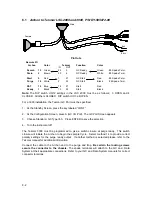
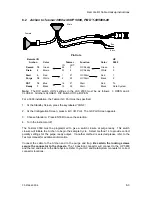
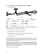
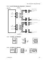
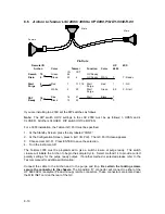
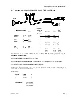
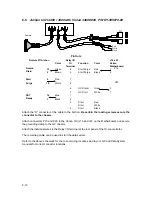
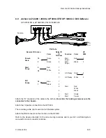
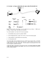
The following drawings are to be used to interface the Archon to the purge and
trap and or gas chromatograph. The interface will allow the Archon, the purge and
trap, and the GC to send and receive correct signals such as the GC ready and
remote start. Each make and model purge and trap and GC will have slightly
different I/O connections, therefore, refer to the drawing which is specific to your
system.
WA R N IN G :
S H O C K H A ZA R D
If any panels must be removed to make cable installations, turn the power
off and unplug the instrument.
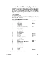
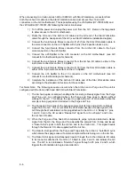
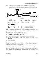
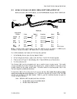
Archon REMOTE I/O connector signal pin-outs.
Pin Number
Signal
Wire Color
1
Logic Ground
Black
2
Logic Ground
Brown
3
Logic Ground
4
Logic Ground
5
Start Purge (no), Relay Output
Red
6
Start Purge (nc)
7
Soil Purging (com)
8
Aux Output (no)
9
Aux Output (nc)
10
Soil Purging2 (com)
11
Serial Output
Reserved
12
Serial Clock
Reserved
13
Serial Load
Reserved
14
Standby (L), Signal Input
Blue
15
Drain (L), Signal Input
Green
16
Emergency Stop (L)
17
Spare
Reserved
18
Start Purge (com), Relay Output
White
19
Soil Purging (no)
20
Soil Purging (nc)
21
Aux Output (com)
22
Soil Purging2 (no)
23
Soil Purging2 (nc)
24
not used
25
+5 Vdc
Reserved
NOTE: All pin outs in Bold are used on the Archon cables.

