System Setup
03-914642-00:6
6-11
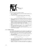
necessary. The standard clearance value set at the factory is 00970. If the
value clearance needs to be readjusted, continue with the next step.
6. Press a Directional Motion key (either "8 " or "2 ") to adjust the clearance. (If
the gripper steps too far, adjust the step size by pressing "5").
DO NOT ALLOW THE GRIPPER TO CONTACT THE GLASS STANDARD
VIALS.
7. Press ENTER to save the position values and complete the routine. The arm
will return to its home position.
After all calibration steps are performed, run the Calibration Test to confirm
system operation. Once this is complete, press the System key twice to exit
the Calibration routine.
6.4.8 Manual Calibration: Coordinate Settings Menu Items
The remaining menu items of the Calibration Setup menu allow manual
calibration of specific positions of the robotic arm and gripper. These are used
less frequently than the automated routines, primarily in the initial instrument
setup and particular troubleshooting situations. These routines allow the user to
move the arm or gripper incrementally until the user determines that the correct
position has been achieved. The user then saves the position coordinates to the
Archon memory.
The routines also allow the user to directly enter a position value determined by
other means. Note that the original positional settings determined at the factory
during the instrument's manufacture are recorded on the reference sheet
attached to the inside of the Archon right chassis panel. In certain instances, it
may be useful to directly re-enter these original values through the Manual
Calibration menu items.
When a manual calibration routine is chosen from the Calibration Setup menu,
the screen will display a new Coordinate Settings menu of the general format
shown below. The title and other minor features will differ to be appropriate for the
task. The menu allows the user to adjust positions along one axis at a time. The
axis currently addressed is shown on the last (fourth) line with the numeric step
value of the current position. The second and third menu lines list the numeric
commands for moving the arm or gripper along that axis.
(Keypad display figure)
* (Title will vary) *
1- Home 3-Step (Jog) 0- Grip
5- Step Size xxx 7- Train
Front/Rear xxxxx (Left/Right) (Vertical)
1. Inspect the positioning of the gripper around the vial and determine if the
horizontal positioning along the Left/Right axis or the Front/Rear axis should
be improved. If not, skip to Step 7.
2. If the gripper position around the vial is to be recalibrated, press an Arrow key
to select the desired horizontal axis.
3. Press "3" as necessary to enter the Step mode.
4. Press a Directional Motion key to adjust the Gripper position. (If the gripper
steps too far, adjust the step size by pressing "5").

