CIB UNIGAS - M039177CA
40
Check of the detection current (with printed circuit)
Seasonal stop
To stop the burner in the seasonal stop, proceed as follows:
1
turn the burner’s main switch to 0 (Off position)
2
disconnect the power mains
3
close the fuel cock of the supply line
Burner’s disposal
In case of disposal, follow the instructions according to the laws in force in your country about the “Disposal of materials”.
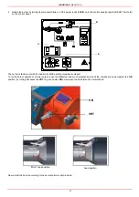
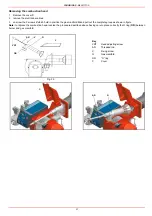
To check the detection signal remove the bridge
on “TEST ER” or “TEST FC” and connect a micro
ammeter when Fig. 40. If the signal is less than
the value indicated, check the position of the
detection electrode or detector, the electrical con-
tacts and, if necessary, replace the electrode or
the UV detector.
Fig. 40
Control box
Minimum detection
signal
Siemens LFL1.3..
6µA (with electrode)
Siemens LFL1.3.. 70µA (with UV detector)
ER
FC
+ µA -
- µA +
UV detector
electrode
Summary of Contents for TP512A
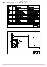
Page 43: ...CIB UNIGAS M039177CA 43 Wiring diagram 21 001 2 Progressive burners ...
Page 44: ...CIB UNIGAS M039177CA 44 Wiring diagram 21 001 2 Fully modulating burners ...
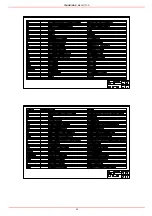
Page 46: ...CIB UNIGAS M039177CA 46 ...
Page 47: ...CIB UNIGAS M039177CA 47 ...
Page 48: ...CIB UNIGAS M039177CA 48 ...
Page 49: ...CIB UNIGAS M039177CA 49 WIRING DIAGRAM Cod 09 315 1 Burners type TP525A Mod M MD x xx x 1 xx ...
Page 50: ...CIB UNIGAS M039177CA 50 ...
Page 51: ...CIB UNIGAS M039177CA 51 ...
Page 52: ...CIB UNIGAS M039177CA 52 ...
Page 55: ...CIB UNIGAS M039177CA 55 ...
Page 56: ......


