CIB UNIGAS - M039177CA
27
2
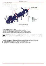
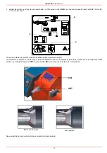
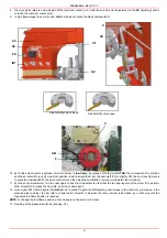
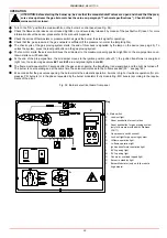
startup the burner by turning its main switch A to on: if the burner locks (LED B on in the control panel) press the RESET button (C)
on the control panel.
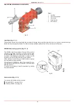
The burner is factory-set with the head in its MAX position (maximum outuput).
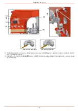
To let the burner operate at a lower output, loose the VB screw and move progressively back the combustion head towards the MIN
position, by turning clockwise the VRT ring nut. Fasten VB screw when the adjustment is accomplished.
Now, adjust the burner according to the servocontrol model provided.
A
C
B
VRT
VB
“MAX” head position
head position
Summary of Contents for TP512A
Page 43: ...CIB UNIGAS M039177CA 43 Wiring diagram 21 001 2 Progressive burners ...
Page 44: ...CIB UNIGAS M039177CA 44 Wiring diagram 21 001 2 Fully modulating burners ...
Page 46: ...CIB UNIGAS M039177CA 46 ...
Page 47: ...CIB UNIGAS M039177CA 47 ...
Page 48: ...CIB UNIGAS M039177CA 48 ...
Page 49: ...CIB UNIGAS M039177CA 49 WIRING DIAGRAM Cod 09 315 1 Burners type TP525A Mod M MD x xx x 1 xx ...
Page 50: ...CIB UNIGAS M039177CA 50 ...
Page 51: ...CIB UNIGAS M039177CA 51 ...
Page 52: ...CIB UNIGAS M039177CA 52 ...
Page 55: ...CIB UNIGAS M039177CA 55 ...
Page 56: ......

