CIB UNIGAS - M039177CA
38
Adjusting the electrodes
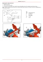
Important Note: Check the ignition and detection electrodes after removing/adjusting the combustion head.
The gap between the ignition electrodes must be 4mm.
Replacing the ignition electrodes
t
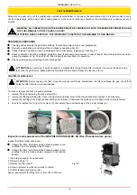
To replace the ignition electrodes, proceed as follows:
1
remove the burner cover
2
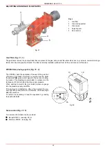
loose the nuts that fasten;the electrodes group to the combustion head (A);
3
disconnect the electrodes cables (B);
4
loose the security dowes of the adjusting ring nut (C);
5
shift the electrodes group back to the outside and remove the combustion head (D),
6
loose the screw of th eignition electrodes support (E);
7
remove the electrodes and replace them paying attention to the measures showed in figure (F-G).
ATTENTION: avoid the ignition and detection electrodes to contact metallic parts (blast tube, head, etc.), otherwise the boi-
ler’s operation would be compromised. Check the electrodes position after any intervention on the combustion head.
ATTENTION: avoid the ignition and detection electrodes to contact metallic parts (blast tube, head, etc.), otherwise the boi-
ler’s operation would be compromised. Check the electrodes position after any intervention on the combustion head.
A
B
C
D
E
F
G
Detection electrode
ignition electrodes
4 mm
Fig. 37
4mm
25mm
25mm
Summary of Contents for TP512A
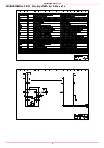
Page 43: ...CIB UNIGAS M039177CA 43 Wiring diagram 21 001 2 Progressive burners ...
Page 44: ...CIB UNIGAS M039177CA 44 Wiring diagram 21 001 2 Fully modulating burners ...
Page 46: ...CIB UNIGAS M039177CA 46 ...
Page 47: ...CIB UNIGAS M039177CA 47 ...
Page 48: ...CIB UNIGAS M039177CA 48 ...
Page 49: ...CIB UNIGAS M039177CA 49 WIRING DIAGRAM Cod 09 315 1 Burners type TP525A Mod M MD x xx x 1 xx ...
Page 50: ...CIB UNIGAS M039177CA 50 ...
Page 51: ...CIB UNIGAS M039177CA 51 ...
Page 52: ...CIB UNIGAS M039177CA 52 ...
Page 55: ...CIB UNIGAS M039177CA 55 ...
Page 56: ......


