CIB UN
IGA
S
- M039177
CA
10
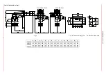
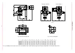
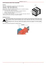
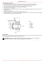
* Fit a counterflange between burner and boiler. As an alternative, make a smaller hole H, but greather than Y and fit the blast tube from the internal side of boiler.
Fig. 7
Fig. 8
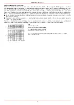
Fig. 9: Bellows unit drilling plate
Fig. 10 - Boiler’s drilling plate
A
B
C
D
E
F
G
H
I
L
M
N
P
Q
Y
TP512A
160
520
910
694
230
530
340
380
517
568
M14
335
390
160
286
TP515A
160
520
910
694
230
530
380
420
517
568
M14
335
390
160
312
TP520A
160
520
910
694
230
530
400
440
517
568
M14
335
390
160
328
TP525A
160
520
910
694
230
530
434
474*
517
568
M14
335
390
160
328
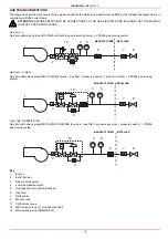
COLD AIR+HOT AIR
COLD AIR ONLY
Summary of Contents for TP512A
Page 43: ...CIB UNIGAS M039177CA 43 Wiring diagram 21 001 2 Progressive burners ...
Page 44: ...CIB UNIGAS M039177CA 44 Wiring diagram 21 001 2 Fully modulating burners ...
Page 46: ...CIB UNIGAS M039177CA 46 ...
Page 47: ...CIB UNIGAS M039177CA 47 ...
Page 48: ...CIB UNIGAS M039177CA 48 ...
Page 49: ...CIB UNIGAS M039177CA 49 WIRING DIAGRAM Cod 09 315 1 Burners type TP525A Mod M MD x xx x 1 xx ...
Page 50: ...CIB UNIGAS M039177CA 50 ...
Page 51: ...CIB UNIGAS M039177CA 51 ...
Page 52: ...CIB UNIGAS M039177CA 52 ...
Page 55: ...CIB UNIGAS M039177CA 55 ...
Page 56: ......

