CIB UNIGAS - M039177CA
32
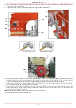
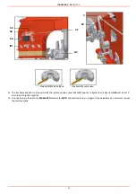
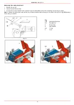
14 The low flame position must never match the ignition position, (see index ID1 position in figure) that is why cam AB must be set 5°
more than the ignition position.
15 Turn the burner off, switch the MAN/AUTO selector to lAUTO and start the burner up again. If the adjustment is not correct, repeat
the previous steps.
ID1
VF
PA
SC
SV
GV
ID2
V
SV
Gas butterfly valve closed
Gas butterfly valve open
Summary of Contents for TP512A
Page 43: ...CIB UNIGAS M039177CA 43 Wiring diagram 21 001 2 Progressive burners ...
Page 44: ...CIB UNIGAS M039177CA 44 Wiring diagram 21 001 2 Fully modulating burners ...
Page 46: ...CIB UNIGAS M039177CA 46 ...
Page 47: ...CIB UNIGAS M039177CA 47 ...
Page 48: ...CIB UNIGAS M039177CA 48 ...
Page 49: ...CIB UNIGAS M039177CA 49 WIRING DIAGRAM Cod 09 315 1 Burners type TP525A Mod M MD x xx x 1 xx ...
Page 50: ...CIB UNIGAS M039177CA 50 ...
Page 51: ...CIB UNIGAS M039177CA 51 ...
Page 52: ...CIB UNIGAS M039177CA 52 ...
Page 55: ...CIB UNIGAS M039177CA 55 ...
Page 56: ......

