CIB UNIGAS - M039177CA
37
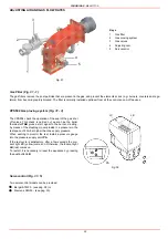
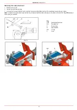
Removing the combustion head
1
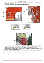
Remove the cover C.
2
remove the electrodes cables;
3
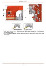
unscrew the 3 screws V which hold in position the gas manifold G and pull out the complete group as shown in figure.
Note: to replace the combustion head reverse the procedure described above having care to place correctly the O ring (OR) between
burner and gas manifold.
Fig. 36
Key
VRT
Head adjusting screw
AR
Threaded rod
V
Fixing screw
G
Gas manifold
OR
“O” ring
C
Cover
V
C
G
AR
OR
VRT
C
AR
G
Summary of Contents for TP512A
Page 43: ...CIB UNIGAS M039177CA 43 Wiring diagram 21 001 2 Progressive burners ...
Page 44: ...CIB UNIGAS M039177CA 44 Wiring diagram 21 001 2 Fully modulating burners ...
Page 46: ...CIB UNIGAS M039177CA 46 ...
Page 47: ...CIB UNIGAS M039177CA 47 ...
Page 48: ...CIB UNIGAS M039177CA 48 ...
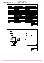
Page 49: ...CIB UNIGAS M039177CA 49 WIRING DIAGRAM Cod 09 315 1 Burners type TP525A Mod M MD x xx x 1 xx ...
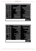
Page 50: ...CIB UNIGAS M039177CA 50 ...
Page 51: ...CIB UNIGAS M039177CA 51 ...
Page 52: ...CIB UNIGAS M039177CA 52 ...
Page 55: ...CIB UNIGAS M039177CA 55 ...
Page 56: ......

