4
3)
GENERAL INSTRUCTIONS DEPENDING ON FUEL USED
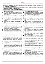
3a) ELECTRICAL CONNECTION
z
For safety reasons the unit must be efficiently earthed and
installed as required by current safety regulations.
z
It is vital that all saftey requirements are met. In case of any
doubt, ask for an accurate inspection of electrics by qualified
personnel, since the manufacturer cannot be held liable for
damages that may be caused by failure to correctly earth the
equipment.
z
Qualified personnel must inspect the system to make sure
that it is adequate to take the maximum power used by the
equipment shown on the equipment rating plate. In particular,
make sure that the system cable cross section is adequate
for the power absorbed by the unit.
z
No adaptors, multiple outlet sockets and/or extension cables
are permitted to connect the unit to the electric mains.
z
An omnipolar switch shall be provided for connection to
mains, as required by the current safety regulations.
z
The use of any power-operated component implies obser-
vance of a few basic rules, for example:
♦
do not touch the unit with wet or damp parts of the body
and/or with bare feet;
♦
do not pull electric cables;
♦
do not leave the equipment exposed to weather (rain, sun,
etc.) unless expressly required to do so;
♦
do not allow children or inexperienced persons to use equi-
pment;
z
The unit input cable shall not be replaced by the user.
In case of damage to the cable, switch off the unit and contact
qualified personnel to replace.
When the unit is out of use for some time the electric switch sup-
plying all the power-driven components in the system (i.e. pumps,
burner, etc.) should be switched off.
3b) FIRING WITH GAS, LIGHT OIL OR OTHER FUELS
GENERAL
z
The burner shall be installed by qualified personnel and in
compliance with regulations and provisions in force; wrong
installation can cause injuries to people and animals, or
damage to property, for which the manufacturer cannot be
held liable.
z
Before installation, it is recommended that all the fuel supply
system pipes be carefully cleaned inside, to remove foreign
matter that might impair the burner operation.
z
Before the burner is commissioned, qualified personnel
should inspect the following:
a
the fuel supply system, for proper sealing;
b
the fuel flow rate, to make sure that it has been set based on
the firing rate required of the burner;
c
the burner firing system, to make sure that it is supplied for
the designed fuel type;
d
the fuel supply pressure, to make sure that it is included in
the range shown on the rating plate;
e
the fuel supply system, to make sure that the system dimen-
sions are adequate to the burner firing rate, and that the
system is equipped with all the safety and control devices
required by the regulations in force.
z
When the burner is to remain idle for some time, the fuel sup-
ply tap or taps should be closed.
SPECIAL INSTRUCTIONS FOR USING GAS
Have qualified personnel inspect the installation to ensure that:
a
the gas delivery line and train are in compliance with the
regulations and provisions in force;
b
all gas connections are tight;
c
the boiler room ventilation openings are such that they
ensure the air supply flow required by the current regulations,
and in any case are sufficient for proper combustion.
z
Do not use gas pipes to earth electrical equipment.
z
Never leave the burner connected when not in use. Always
shut the gas valve off.
z
In case of prolonged absence of the user, the main gas deli-
very valve to the burner should be shut off.
Precautions if you can smell gas
a
do not operate electric switches, the telephone, or any other
item likely to generate sparks;
b
immediately open doors and windows to create an air flow to
purge the room;
c
close the gas valves;
d
contact qualified personnel.
z
Do not obstruct the ventilation openings of the room where
gas appliances are installed, to avoid dangerous conditions
such as the development of toxic or explosive mixtures.
Summary of Contents for TP512A
Page 43: ...CIB UNIGAS M039177CA 43 Wiring diagram 21 001 2 Progressive burners ...
Page 44: ...CIB UNIGAS M039177CA 44 Wiring diagram 21 001 2 Fully modulating burners ...
Page 46: ...CIB UNIGAS M039177CA 46 ...
Page 47: ...CIB UNIGAS M039177CA 47 ...
Page 48: ...CIB UNIGAS M039177CA 48 ...
Page 49: ...CIB UNIGAS M039177CA 49 WIRING DIAGRAM Cod 09 315 1 Burners type TP525A Mod M MD x xx x 1 xx ...
Page 50: ...CIB UNIGAS M039177CA 50 ...
Page 51: ...CIB UNIGAS M039177CA 51 ...
Page 52: ...CIB UNIGAS M039177CA 52 ...
Page 55: ...CIB UNIGAS M039177CA 55 ...
Page 56: ......

