CIB UNIGAS - M039177CA
39
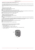
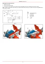
Replacing the detection electrode
To replace the detection electrode, proceed as follows:
1
remove the combustion head according to the procedure on paragraph “Removing the combustion head”;
2
by means of an allen key, loose the fixing screws of the detection electrode ER and replace it;
3
replace the combustion head.
Checking the detection current
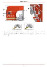
To check the detection signal follow the scheme in Fig. 38 or Fig. 39. If the signal is less than the value indicated, check the position of
the detection electrode or detector, the electrical contacts and, if necessary, replace the electrode or the detector.
ATTENTION: avoid the ignition and detection electrodes to contact metallic parts (blast tube, head, etc.), otherwise
the boiler’s operation would be compromised. Check the electrodes position after any intervention on the combustion
head.
Control box
Minimum detection signal
Siemens LFL1.3..
6µA (with electrode)
Siemens LFL1.3..
70µA with UV detector)
Fig. 38: Detection by electrode
Fig. 39: Detection by photocell QRA..
ER
ER
TERMINAL BOARD
MC
SCALA µA DC
27
TERMINAL BOARD
MC
Summary of Contents for TP512A
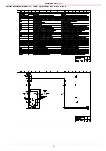
Page 43: ...CIB UNIGAS M039177CA 43 Wiring diagram 21 001 2 Progressive burners ...
Page 44: ...CIB UNIGAS M039177CA 44 Wiring diagram 21 001 2 Fully modulating burners ...
Page 46: ...CIB UNIGAS M039177CA 46 ...
Page 47: ...CIB UNIGAS M039177CA 47 ...
Page 48: ...CIB UNIGAS M039177CA 48 ...
Page 49: ...CIB UNIGAS M039177CA 49 WIRING DIAGRAM Cod 09 315 1 Burners type TP525A Mod M MD x xx x 1 xx ...
Page 50: ...CIB UNIGAS M039177CA 50 ...
Page 51: ...CIB UNIGAS M039177CA 51 ...
Page 52: ...CIB UNIGAS M039177CA 52 ...
Page 55: ...CIB UNIGAS M039177CA 55 ...
Page 56: ......

