CIB UNIGAS - M039177CA
35
OPERATION
z
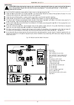
Turn to the “ON” position the main switch A, on the burner’s control panel (see Fig. 34).
z
Check the flame control device is not locked (light B, on) and eventually release it by means of the pushbutton C (reset - for more
information about the device, please refer to the manual’s Appendix).
z
Check the series of thermostats or pressure switches gives the burner the start signal for operating.
z
Check that the gas pressure in the gas network is sufficient (if the pressure is normal, the lamp E lights).
z
The check cycle of the gas proving system starts; the end of this check is signalled by the lamp on the device (see pag. 25). To
unlock the system, press the reset pushbutton on the gas proving system.
z
The fan motor starts, the servocontrol drives the air damper to the maximum opening position (light G on); the pre-purge time coun-
tdown starts now (30 seconds).
z
At the end of the pre-purgue time, the air damper moves to the ignition position (about 5°), the ignition transformer is energized
(light I on), the solenoid gas valves EV1 and EV2 are energized (lights L and M).
z
The flame must appear within 3 seconds after the gas valves opening, the transformer is de-energized and the light I is turned off.
The burner is now operating and at the same time the servocontrol moves to the hi-flame position (90° - see pag. 26).
z
24 seconds after the gas valves opening, the burner starts the automatic operation: it works in high or low-flame operation (for pro-
gressive PR- burners) or in the phase requested by the burner modulator (Fully modulating - MD buners) according to the require-
ments of the plant.
Fig. 34: Burner’s electrical board front panel
ATTENTION: before starting the burner up, be sure that the manual shutoff valves are open and check that the pres-
sure value upstream the gas train matches the value on paragraph “Technical specifications”). Check that the
mains switch is closed.
Key
A Main switch
B
Lock-out light
C
Reset pushbutton for control box
D
Reset pushbutton for gas proving system
(only for burners provided with Siemens
LDU11)
E
Gas pressure switch consent
F
Lock-out light for gas proving system
G
Hi-flame operation light
H
Lo-flame operation light
I
Ignition transformer operation light
L
EV2 opening light
M
EV1 opening light
N
Fan motor overload tripped light
O
Burner in stand-by light
P
Burner Modulator (only on fully modula-
ting burners)
M
F
D
P
A
C
E
L
N
G
H
B
I
O
Summary of Contents for TP512A
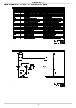
Page 43: ...CIB UNIGAS M039177CA 43 Wiring diagram 21 001 2 Progressive burners ...
Page 44: ...CIB UNIGAS M039177CA 44 Wiring diagram 21 001 2 Fully modulating burners ...
Page 46: ...CIB UNIGAS M039177CA 46 ...
Page 47: ...CIB UNIGAS M039177CA 47 ...
Page 48: ...CIB UNIGAS M039177CA 48 ...
Page 49: ...CIB UNIGAS M039177CA 49 WIRING DIAGRAM Cod 09 315 1 Burners type TP525A Mod M MD x xx x 1 xx ...
Page 50: ...CIB UNIGAS M039177CA 50 ...
Page 51: ...CIB UNIGAS M039177CA 51 ...
Page 52: ...CIB UNIGAS M039177CA 52 ...
Page 55: ...CIB UNIGAS M039177CA 55 ...
Page 56: ......


