CIB UNIGAS - M039177CA
36
At least once a year carry out the maintenance operations listed below. In the case of seasonal servicing, it is recommended to carry
out the maintenance at the end of each heating season; in the case of continuous operation the maintenance is carried out every 6
months.
PERIODICAL SERVICING
z
Cleaning and examining the gas filter cartridge, if necessary replace it (see next paragraphs).
z
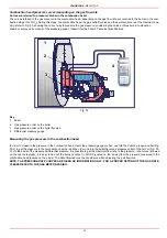
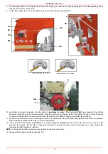
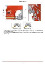
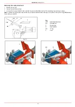
Removal, examination and cleaning of the combustion head (see Fig. 36)
z
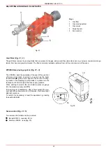
Check of ignition electrode, cleaning, adjustment and, if necessary, replacement (see Fig. 37)
z
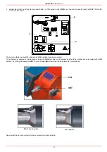
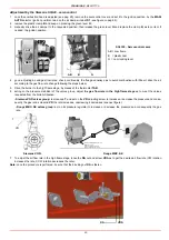
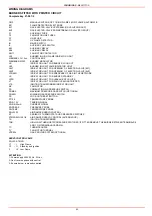
Check of detection electrode, cleaning, adjustment and, if necessary, replacement; in case of doubt, check the detection circuit fol-
lowing the diagram in Fig. 39 and Fig. 40, after turning the burner back into operation.
z
Cleaning and greasing of leverages and rotating parts.
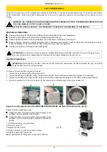
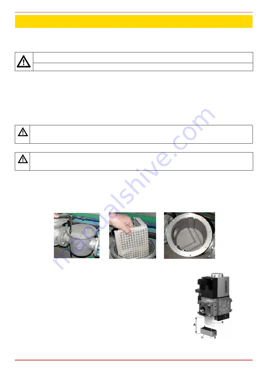
Gas filter maintenance
To clean or remove the filter, proceed as follows:
1
remove the cap unscrewing the fixing screws (A);
2
remove the filtering cartridge (B), clean it using water and soap, blow it with compressed air(or replace it, if necessary)
3
replace the cartridge in its proper position taking care to place it inbetween the guides as not to hamper the cap replacement;
4
be sure to replace the Or ring into its place (C) and replace the cover fastening by the proper screws (A).
Inspection and replacement of the
MULTIBLOC DUNGS MBC..SE filter (Threaded valves group)
WARNING: ALL OPERATIONS ON THE BURNER MUST BE CARRIED OUT WITH THE MAINS DISCONNECTED AND
THE FUEL MANAUL CUTOFF VALVES CLOSED!
ATTENTION: READ CAREFULLY THE “WARNINGS” CHAPTER AT THE BEGINNIG OF THIS MANUAL.
ATTENTIONwhen servicing, if it was necessary to disassemble the gas train parts, remember to execute the gas proving
test, once the gas train is reassembled, according to the procedure imposed by the law in force.
ATTENTION: Before opening the filter, close the manual cutoff valve downstream the filter and bleed the gas; check that
inside the filter there is no pressurised gas.
A
B
C
Inspect the filter at least once a year.
z
Change the filter, if pressure value between pressure con-
nections 1 and 2 is greather than 10 mbar.
z
Change the filter, if pressure value between pressure con-
nections 1 and 2 is twice as high compared to the last ins-
pection.
1. Interrupt gas supply: close ball valve
2. Remove screws 1-2
3. Replace the filter insert 3
4. Screw in screws 1-2 without use force to fasten.
5. Perform leakage and funcion test.
Space requirements for fitting filter, A: from 150 to 230 mm.
Fig. 35
PART III: MAINTENANCE
Summary of Contents for TP512A
Page 43: ...CIB UNIGAS M039177CA 43 Wiring diagram 21 001 2 Progressive burners ...
Page 44: ...CIB UNIGAS M039177CA 44 Wiring diagram 21 001 2 Fully modulating burners ...
Page 46: ...CIB UNIGAS M039177CA 46 ...
Page 47: ...CIB UNIGAS M039177CA 47 ...
Page 48: ...CIB UNIGAS M039177CA 48 ...
Page 49: ...CIB UNIGAS M039177CA 49 WIRING DIAGRAM Cod 09 315 1 Burners type TP525A Mod M MD x xx x 1 xx ...
Page 50: ...CIB UNIGAS M039177CA 50 ...
Page 51: ...CIB UNIGAS M039177CA 51 ...
Page 52: ...CIB UNIGAS M039177CA 52 ...
Page 55: ...CIB UNIGAS M039177CA 55 ...
Page 56: ......


