M03177CA
2
TABLE OF CONTENTS
WARNINGS ................................................................................................................................................................ 3
PART I: INSTALLATION MANUAL .......................................................................................................................... 5
GENERAL FEATURES ................................................................................................................................................................... 5
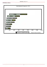
How to interpret the burner’s “Performance curve” ......................................................................................................................... 6
BURNERS SPECIFICATIONS ....................................................................................................................................................... 7
Technical specifications ................................................................................................................................................................ 7
Country and usefulness gas categories .......................................................................................................................................... 8
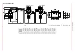
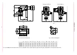
Overall dimensions ......................................................................................................................................................................... 9
Performance Curves ..................................................................................................................................................................... 11
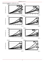
Pressure in the Network / gas flow rate curves ............................................................................................................................ 12
MOUNTING AND CONNECTING THE BURNER ........................................................................................................................ 13
Packing ......................................................................................................................................................................................... 13
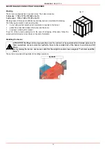
Handling the burner ...................................................................................................................................................................... 13
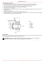
Fitting the burner to the boiler ....................................................................................................................................................... 14
Fan installation .............................................................................................................................................................................. 14
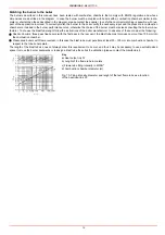
Matching the burner to the boiler .................................................................................................................................................. 15
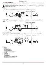
GAS TRAIN CONNECTIONS ....................................................................................................................................................... 16
Assembling the gas grain .............................................................................................................................................................. 17
ELECTRICAL CONNECTIONS .................................................................................................................................................... 20
Electrical wiring diagram for burners provided with printed circuit (standard configuration) .......................................................... 21
Electrical wiring diagram for burners with no printed circuit provided ........................................................................................... 22
Rotation of fan motor .................................................................................................................................................................... 22
Combustion head pressure curves depending on the gas flow rate ............................................................................................. 23
Measuring the gas pressure in the combustion head ................................................................................................................... 23
Pressure in combustion head - gas flow rate curves ................................................................................................................. 24
ADJUSTING AIR AND GAS FLOW RATES ................................................................................................................................. 25
Gas Filter .................................................................................................................................................................................... 25
VPS504 Gas proving system ....................................................................................................................................................... 25
Servocontrol .................................................................................................................................................................................. 25
Air and gas flow rate adjustements ............................................................................................................................................... 26
Adjustment by the Berger STM30.. servocontrol .......................................................................................................................... 28
Adjustment by the Siemens SQL33.. servocontrol ....................................................................................................................... 30
Calibration of air and gas pressure switches ................................................................................................................................ 33
Calibration of air pressure switch .................................................................................................................................................. 33
Calibration of minimum gas pressure switch ................................................................................................................................ 33
Calibrating the maximum gas pressure switch (when provided) ................................................................................................... 33
PART II: OPERATION ............................................................................................................................................. 34
OPERATION ................................................................................................................................................................................. 35
PART III: MAINTENANCE ....................................................................................................................................... 36
PERIODICAL SERVICING ........................................................................................................................................................... 36
Gas filter maintenance .................................................................................................................................................................. 36
Inspection and replacement of the MULTIBLOC DUNGS MBC..SE filter (Threaded valves group) ............................................ 36
Adjusting the electrodes ................................................................................................................................................................ 38
Replacing the electrodes ............................................................................................................................................................... 38
Checking the detection current ..................................................................................................................................................... 39
Seasonal stop ............................................................................................................................................................................... 40
Burner disposal ............................................................................................................................................................................. 40
TROUBLESHOOTING .................................................................................................................................................................. 41
WIRING DIAGRAMS .................................................................................................................................................................... 42
SPARE PARTS ............................................................................................................................................................................. 53
APPENDIX ................................................................................................................................................................ 54
Summary of Contents for TP512A
Page 43: ...CIB UNIGAS M039177CA 43 Wiring diagram 21 001 2 Progressive burners ...
Page 44: ...CIB UNIGAS M039177CA 44 Wiring diagram 21 001 2 Fully modulating burners ...
Page 46: ...CIB UNIGAS M039177CA 46 ...
Page 47: ...CIB UNIGAS M039177CA 47 ...
Page 48: ...CIB UNIGAS M039177CA 48 ...
Page 49: ...CIB UNIGAS M039177CA 49 WIRING DIAGRAM Cod 09 315 1 Burners type TP525A Mod M MD x xx x 1 xx ...
Page 50: ...CIB UNIGAS M039177CA 50 ...
Page 51: ...CIB UNIGAS M039177CA 51 ...
Page 52: ...CIB UNIGAS M039177CA 52 ...
Page 55: ...CIB UNIGAS M039177CA 55 ...
Page 56: ......

