CIB UNIGAS - M039177CA
31
8
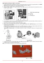
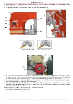
the air and gas rate are now adjusted at the maximum output, go on with the point to point adjustment on the SV adjusting cam as
to reach the minimum output point.
9
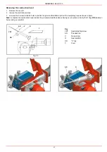
In high flame stage, the servocontrol AB cam does not press the black microswitch C;
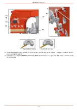
10 as for the point-to-point regulation, drive the burner to low flame, by means of the thermostat TAB: the microswitch C is still free
and the servocontrol is on its maximum position; insert a screwdriver into the cam cleft F, turn sligthly CW the cam (see figure) as
to press the microswitch C: the servocontrol moves the adjusting cam SV to a lower point (towards the minimum);
.
11 by measn of a screwdriver, turn the cam again to free the microswitch in order that the two bearings meet the screw V to de adju-
sted: screw V to increase the flow rate, unscrew to decrease it;
12 move again CW (refer to figure) the AB cam as to press C again: the SV adjusting cam moves to the minimum, procced as in the
prevoius step to adjust the low rate in a lower point: screw V to increase the rate, unscrew to decrease; go on this way until the
requested low flame position is reached.
NOTE: to change the low flame position, act exclusively on the servocontrol cam.
13 Now adjust the pressure switches (see pag. 33).
ID1
VF
PA
SC
SV
GV
ID2
V
SV
Gas butterfly valve closed
Gas butterfly valve open
C
AB
F
Summary of Contents for TP512A
Page 43: ...CIB UNIGAS M039177CA 43 Wiring diagram 21 001 2 Progressive burners ...
Page 44: ...CIB UNIGAS M039177CA 44 Wiring diagram 21 001 2 Fully modulating burners ...
Page 46: ...CIB UNIGAS M039177CA 46 ...
Page 47: ...CIB UNIGAS M039177CA 47 ...
Page 48: ...CIB UNIGAS M039177CA 48 ...
Page 49: ...CIB UNIGAS M039177CA 49 WIRING DIAGRAM Cod 09 315 1 Burners type TP525A Mod M MD x xx x 1 xx ...
Page 50: ...CIB UNIGAS M039177CA 50 ...
Page 51: ...CIB UNIGAS M039177CA 51 ...
Page 52: ...CIB UNIGAS M039177CA 52 ...
Page 55: ...CIB UNIGAS M039177CA 55 ...
Page 56: ......

