CIB UNIGAS - M039177CA
33
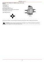
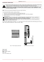
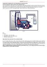
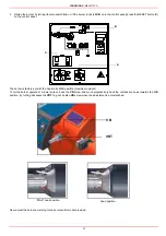
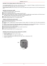
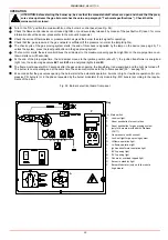
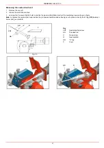
Calibration of air and gas pressure switches (Fig. 31- 2 - 5)
The air pressure switch locks the control box if the air pressure is not the one requested. If it happens, unlock the burner by means of
the control box unlock pushbutton, placed on the burner control panel.
The gas pressure switches check the pressure to avoid the burner operate when the pressure value is not in the requested pressure
range.
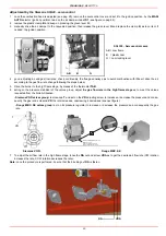
Calibration of air pressure switch
To calibrate the air pressure switch, proceed as follows:
z
Remove the transparent plastic cap.
z
Once air and gas setting have been accomplished, startup the burner.
z
During the pre-purge phase o the operation, turn slowly the adjusting ring nut VR in the clockwise direction until the burner lockout,
then read the value on the pressure switch scale and set it to a value reduced by 15%.
z
Repeat the ignition cycle of the burner and check it runs properly.
z
Refit the transparent plastic cover on the pressure switch.
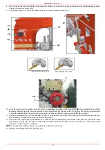
Calibration of minimum gas pressure switch
As for the gas pressure switch calibration, proceed as follows:
z
Remove the transparent plastic cap.
z
While the burner is operating at the maximum output, test the gas pressure on the pressure port of the minimum gas pressure
switch.
z
Slowly close the manual shut-off valve (placed upstream the pressure switch, see gas train installation diagram), until the detected
pressure is reduced by 50%. Pay attention that the CO value in the flue gas does not increase.
z
Check that the burner is operating correctly.
z
Screw down the pressure switch adjusting ring nut until the burner lockout.
z
Fully open the manual shut-off valve.
z
Refit the transparent plastic cover on the pressure switch.
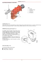
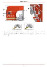
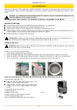
Calibrating the maximum gas pressure switch (when provided)
To calibrate the high pressure switch, proceed as follows:
1
remove the plastic cover;
2
measure the gas pressure in the network, when flame is off;
3
by means of the adjusting ring nut VR, set the value read on step 2, increased by the 30%;
4
replace the plastic cover.
Fig. 33
VR
Summary of Contents for TP512A
Page 43: ...CIB UNIGAS M039177CA 43 Wiring diagram 21 001 2 Progressive burners ...
Page 44: ...CIB UNIGAS M039177CA 44 Wiring diagram 21 001 2 Fully modulating burners ...
Page 46: ...CIB UNIGAS M039177CA 46 ...
Page 47: ...CIB UNIGAS M039177CA 47 ...
Page 48: ...CIB UNIGAS M039177CA 48 ...
Page 49: ...CIB UNIGAS M039177CA 49 WIRING DIAGRAM Cod 09 315 1 Burners type TP525A Mod M MD x xx x 1 xx ...
Page 50: ...CIB UNIGAS M039177CA 50 ...
Page 51: ...CIB UNIGAS M039177CA 51 ...
Page 52: ...CIB UNIGAS M039177CA 52 ...
Page 55: ...CIB UNIGAS M039177CA 55 ...
Page 56: ......

