CIB UNIGAS - M039177CA
17
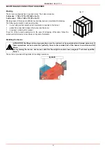
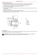
Assembling the gas grain
To assemble the gas train, proceed as follows:
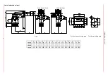
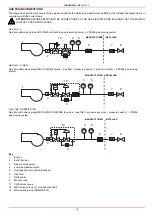
Fig. 14 - Example of gas train
To mount the gas train, proceed as follows:
1-a) in case of threaded joints: use proper seals according to the gas used;
1-b) in case of flanged joints: place a gasket (no. 1A..1E - Fig. 14) between the elements
NOTE: the bellow joint, the manual cock and the gaskets are not part of the standard supply.
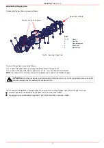
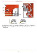
The procedures of installation fo the gas valves are showed in the next paragraphs, according to the gas train used:
z
threaded gas trains with Multibloc Dungs MBC..SE 1200 or Siemens VGD20..
z
flanged gas trains with Multibloc Dungs MBC..SE 1900-3100-5000 or Siemens VGD40..
ATTENTION: once the gas train is mounted according to the diagram on Fig. 14, the gas proving test mus be perfor-
med, according to the procedure set by the laws in force.
1A
5
1B
4
1C
2
1D
1E
3
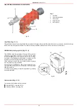
Keys
1A..1E
Gasket
2
Gas filter
3
Gas valves group
4
Bellow joint
5
Manual cock
”direction” arrows for installation
gas supply network
Summary of Contents for TP512A
Page 43: ...CIB UNIGAS M039177CA 43 Wiring diagram 21 001 2 Progressive burners ...
Page 44: ...CIB UNIGAS M039177CA 44 Wiring diagram 21 001 2 Fully modulating burners ...
Page 46: ...CIB UNIGAS M039177CA 46 ...
Page 47: ...CIB UNIGAS M039177CA 47 ...
Page 48: ...CIB UNIGAS M039177CA 48 ...
Page 49: ...CIB UNIGAS M039177CA 49 WIRING DIAGRAM Cod 09 315 1 Burners type TP525A Mod M MD x xx x 1 xx ...
Page 50: ...CIB UNIGAS M039177CA 50 ...
Page 51: ...CIB UNIGAS M039177CA 51 ...
Page 52: ...CIB UNIGAS M039177CA 52 ...
Page 55: ...CIB UNIGAS M039177CA 55 ...
Page 56: ......

