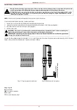
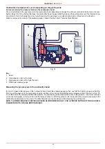
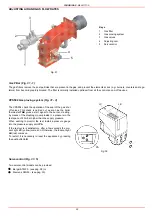
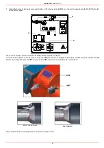
background image

CIB UNIGAS - M039177CA

34

LIMITATIONS OF USE

THE BURNER IS AN APPLIANCE DESIGNED AND CONSTRUCTED TO OPERATE ONLY AFTER BEING CORRECTLY CON-
NECTED TO A HEAT GENERATOR (E.G. BOILER, HOT AIR GENERATOR, FURNACE, ETC.), ANY OTHER USE IS TO BE CONSI-
DERED IMPROPER AND THEREFORE DANGEROUS.

THE USER MUST GUARANTEE THE CORRECT FITTING OF THE APPLIANCE, ENTRUSTING THE INSTALLATION OF IT TO
QUALIFIED PERSONNEL AND HAVING THE FIRST COMMISSIONING OF IT CARRIED OUT BY A SERVICE CENTRE AUTHORI-
SED BY THE COMPANY MANUFACTURING THE BURNER.

A FUNDAMENTAL FACTOR IN THIS RESPECT IS THE ELECTRICAL CONNECTION TO THE GENERATOR’S CONTROL AND
SAFETY UNITS (CONTROL THERMOSTAT, SAFETY, ETC.) WHICH GUARANTEES CORRECT AND SAFE FUNCTIONING OF
THE BURNER.

THEREFORE, ANY OPERATION OF THE APPLIANCE MUST BE PREVENTED WHICH DEPARTS FROM THE INSTALLATION
OPERATIONS OR WHICH HAPPENS AFTER TOTAL OR PARTIAL TAMPERING WITH THESE (E.G. DISCONNECTION, EVEN
PARTIAL, OF THE ELECTRICAL LEADS, OPENING THE GENERATOR DOOR, DISMANTLING OF PART OF THE BURNER).

NEVER OPEN OR DISMANTLE ANY COMPONENT OF THE MACHINE.

OPERATE ONLY THE MAIN SWITCH, WHICH THROUGH ITS EASY ACCESSIBILITY AND RAPIDITY OF OPERATION ALSO
FUNCTIONS AS AN EMERGENCY SWITCH, AND ON THE RESET BUTTON.

IN THE EVENT OF REPEATED LOCKOUTS, DO NOT PERSIST WITH THE RESET BUTTON AND CONTACT QUALIFIED PER-
SONNEL WHO WILL PROCEED TO ELIMINATE THE MALFUNCTION.

WARNING: DURING NORMAL OPERATION THE PARTS OF THE BURNER NEAREST TO THE GENERATOR (COUPLING
FLANGE) CAN BECOME VERY HOT, AVOID TOUCHING THEM SO AS NOT TO GET BURNT.

PART II: OPERATION

Summary of Contents for TP512A

Page 1: ...M039177CA Rev 0 04 2007 BURNERS BRUCIATORI BRULERS BRENNER QUEMADORES ГОРЕЛКИ Gas burners MANUAL OF INSTALLATION USE MAINTENANCE TP90A TP91A TP92A TP93A TP512A TP515A TP520A TP525A ...

Page 2: ... head pressure curves depending on the gas flow rate 23 Measuring the gas pressure in the combustion head 23 Pressure in combustion head gas flow rate curves 24 ADJUSTING AIR AND GAS FLOW RATES 25 Gas Filter 25 VPS504 Gas proving system 25 Servocontrol 25 Air and gas flow rate adjustements 26 Adjustment by the Berger STM30 servocontrol 28 Adjustment by the Siemens SQL33 servocontrol 30 Calibration...

Page 3: ...quipment only shall be used z This unit shall be employed exclusively for the use for which it is meant Any other use shall be considered as improper and therefore dangerous The manufacturer shall not be held liable by agreement or othe rwise for damages resulting from improper installation use and failure to comply with the instructions supplied by the manufactu rer 2 SPECIAL INSTRUCTIONS FOR BUR...

Page 4: ...ls or damage to property for which the manufacturer cannot be held liable z Before installation it is recommended that all the fuel supply system pipes be carefully cleaned inside to remove foreign matter that might impair the burner operation z Before the burner is commissioned qualified personnel should inspect the following a the fuel supply system for proper sealing b the fuel flow rate to mak...

Page 5: ...the supply line passes through the valves group provided with filter and stabiliser This one forces the pressure in the utilisation limits The electric servocontrol 2 that moves proportionally the air damper and the gas butterfly valve uses an adju sting cam 1 with variable shape This one allows the optimisation of the gas flue values as to get an efficient combustion The combu stion head position...

Page 6: ...roper gas train size To check the proper gas train size it is necessary to the available gas pressure value upstream the burner s gas valve Then subtract the backpressure The result is called pgas Draw a vertical line matching the furnace input value 600kW in the example quoted on the x axis as far as intercepitng the network pressure curve according to the installed gas train DN65 in the example ...

Page 7: ...NER VERSION A Standard 7 EQUIPMENT 1 2 valves gas proving system 8 GAS CONNECTION see Specifications 50 Rp2 65 DN65 80 DN80 100 DN100 BURNER TYPE TP90A TP91A TP92A TP93A Output min max kW 320 2300 480 2670 480 3050 550 4100 Fuel Natural gas Category see next paragraph Gas rate min max Stm3 h 34 243 51 283 51 323 58 434 Power supply 230V 3 400V 3N 50Hz Total power consumption kW 0 5 Protection IP40...

Page 8: ... 65 DN65 Gas train 80 ØValves Connection 80 DN80 Gas train 100 ØValves Connection 100 DN100 Operating temperature C 10 50 Storage Temperature C 20 60 Working service Internittent Note1 all gas flow rates are referred to Stm3 h 1013 mbar pressure 15 C temperature and are valid for G20 natural gas nett calorific value 34 02 MJ Stm3 Note2 Maximum gas pressure 500mbar with Siemens VGD gas valves Minim...

Page 9: ...C D E F G H I L M N P Q Y TP90A 148 490 826 606 180 510 234 264 503 425 M12 322 300 160 228 TP91A 148 490 826 606 180 510 265 295 503 425 M12 322 300 160 228 TP92A 148 490 826 606 180 510 269 299 503 425 M12 322 300 160 228 TP93A 148 495 826 606 180 510 304 344 503 425 M12 322 300 160 228 COLD AIR HOT AIR COLD AIR ONLY ...

Page 10: ... 8 Fig 9 Bellows unit drilling plate Fig 10 Boiler s drilling plate A B C D E F G H I L M N P Q Y TP512A 160 520 910 694 230 530 340 380 517 568 M14 335 390 160 286 TP515A 160 520 910 694 230 530 380 420 517 568 M14 335 390 160 312 TP520A 160 520 910 694 230 530 400 440 517 568 M14 335 390 160 328 TP525A 160 520 910 694 230 530 434 474 517 568 M14 335 390 160 328 COLD AIR HOT AIR COLD AIR ONLY ...

Page 11: ...9177CA 11 Performance Curves TP525A TP520A TP515A TP512A TP93A TP92A TP90A TP91A 0 2000 4000 6000 8000 10000 12000 14000 16000 Campo di scelta bruciatore Output diagram air temperature 15 C Range for burner choosing ...

Page 12: ...0 250 300 Rp 2 50 DN65 DN80 DN100 0 20 40 60 80 100 120 50 100 150 200 250 300 350 Rp2 50 DN100 DN80 DN65 0 40 80 120 160 200 50 100 150 200 250 300 350 400 450 500 Rp 2 50 DN65 DN80 DN100 0 50 100 150 200 50 100 150 200 250 300 350 400 450 500 550 Rp 2 50 DN65 DN80 DN100 0 50 100 150 200 250 50 100 150 200 250 300 350 400 450 500 550 600 650 Rp 2 50 DN65 DN80 DN100 0 50 100 150 200 250 300 350 40...

Page 13: ...rain detached but electrically connected to the burner 1 gasket to be inserted between the burner and the boiler 1 envelope containing this manual To get rid of the burner s packing and in the event of scrapping of the latter follow the procedures laid down by current laws on disposal of materials Fig 11 ATTENTION the lfting and moving operations must be carried out by specialised and trained pers...

Page 14: ... bustion head axis 7 install the burner to the boiler 8 fix the burner to the stud bolts by means of the fixing nuts according to Fig 12 9 After fitting the burner to the boiler ensure that the gap between the blast tube and the refractory lining is sealed with appropriate insulating material ceramic fibre cord or refractory cement Fan installation Pay attention when designing the air duct dimensi...

Page 15: ...se the blast tube lenght follow the instructions of the boiler manufacturer In absence of these consider the following z Cast iron boilers three pass flue boilers with the first pass in the rear part the blast tube must protrude no more than 100 mm into the combustion chamber z Pressurised boilers with flame reversal in this case the blast tube must penetrate at least 50 100 mm into combustion cha...

Page 16: ...ilter 7 Bellow joint 8 Manual cock 11 VGD valves group 18 MBC valves group 2 provided with filter 19 MBC valves group DN65 80 100 Gas train 1 Gas train with valves group VGD 20 40 with built in gas pressure governor VPS504 gas proving system Gas train 2 Rp2 Gas train with valves group MBC 1200SE 2 valves gas filter pressure governor pressure switch VPS504 gas proving system Gas train 3 DN65 80 100...

Page 17: ...dard supply The procedures of installation fo the gas valves are showed in the next paragraphs according to the gas train used z threaded gas trains with Multibloc Dungs MBC SE 1200 or Siemens VGD20 z flanged gas trains with Multibloc Dungs MBC SE 1900 3100 5000 or Siemens VGD40 ATTENTION once the gas train is mounted according to the diagram on Fig 14 the gas proving test mus be perfor med accord...

Page 18: ...tted z Connect the reference gas pipe TP in figure to the gas pressure nipples placed on the gas pipe downstream the gas valves gas pres sure must be measured at a distance that must be at least 5 times the pipe size Leave the blowhole free SA in figure Should the spring fitted not permit satisfactory regulation ask one of our service centres for a suitable replacement WARNING removing the four sc...

Page 19: ...ounting 1 Insert setscrews A 2 Insert seals 3 Insert setscrews B 4 Tighten setscrews A B Ensure correct seating of the seal 6 After installation perform leakage and functional test 7 Disassembly in reverse order MOUNTING POSITIONS Fig 20 ATTENTION once the gas train is mounted according to the diagram on Fig 14 the gas proving test mus be perfor med according to the procedure set by the laws in fo...

Page 20: ...hermal cutout Respect the basic safety rules make sure of the connection to the earthing system do not reverse the phase and neutral connections fit a differential thermal magnet switch adequate for connection to the mains ATTENTION before executing the electrical connections pay attention to turn the plant s switch to OFF and be sure that the burner s main switch is in 0 position OFF too Read car...

Page 21: ...er as for the next elements Fig 24 Fig 26 LB Burner s lockout signalling LED LSPG Gas proving system lockout signalling LED 3 In case of modulating burners the 5 6 and 7 terminals on the MA teminal block are already connected to the regulating modula tor mod RWF40 A 4 pole plug coming out from the electrical panel is provided for the temperature and pressure probes connec tions see Fig 25 Note the...

Page 22: ...r The motor should rotate according to the indication on the body In the event of wrong rotation reverse the three phase supply and check again the rotation of the motor NOTE the burners are supplied for three phase 400V supply and in the case of three phase 230V supply it is necessary to modify the electrical connections into the terminal box of the electric motor and replace the overload tripped...

Page 23: ...pressure outlet on the butterfly valve 4 Differential pressure gauge Measuring the gas pressure in the combustion head In order to measure the pressure in the combustion head insert the pressure gauge probes one into the boiler s pressure outlet Fig 30 2 to get the pressure in the combustion chamber and the other one into the butterfly valve s pressure outlet of the burner Fig 30 3 On the basis of...

Page 24: ...250 0 5 10 15 20 25 30 35 40 40 60 80 100 120 140 160 180 200 220 240 260 280 300 0 5 10 15 20 25 30 35 40 45 40 60 80 100 120 140 160 180 200 220 240 260 280 300 320 340 0 5 10 15 20 25 30 35 40 45 50 50 75 100 125 150 175 200 225 250 275 300 325 350 375 400 425 450 0 5 10 15 20 25 30 35 50 100 150 200 250 300 350 400 450 500 0 5 10 15 20 25 30 35 40 50 100 150 200 250 300 350 400 450 500 550 600...

Page 25: ...s valves 4 Adjusting cam 5 Servocontrol VPS504 Gas proving system Fig 31 3 The VPS504 check the operation of the seal of the gas shut off valves This check is carried out as soon as the boiler thermostat TAB gives a start signal to the burner creating by means of the diaphragm pump inside it a pressure in the test space of 20 mbar higher than the supply pressure When wishing to monitor the test in...

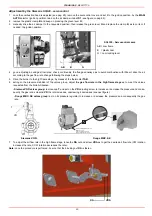
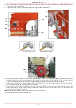
Page 26: ...maximum and minimum set the shape of the adjusting cam foil The adjusting cam sets the air gas ratio in those points regulating the opening closing of the butterfly gas valve z Set now the low flame output acting on the low flame microswitch of the servocontrol cam III for Berger STM30 in order to avoid the low flame output increasing too much or that the flues temperature gets too low to cause co...

Page 27: ...ory set with the head in its MAX position maximum outuput To let the burner operate at a lower output loose the VB screw and move progressively back the combustion head towards the MIN position by turning clockwise the VRT ring nut Fasten VB screw when the adjustment is accomplished Now adjust the burner according to the servocontrol model provided A C B VRT VB MAX head position head position ...

Page 28: ...e as to meet the values requested from the boiler utilisation Siemens VGD valves group remove cap T and act on the VR adjusting screw to increase or decrease the pressure and conse quently the gas rate screwind VR the rate increases unscrewing it decreases see next figure Dungs MBC SE valves group act on its pressure regulator to increase or decrease the pressure and consequently the gas rate 5 To...

Page 29: ...V to increase the rate unscrew to decrease 10 Move again cam III towards the minimum to meet the next screw on the adjusting cam and repeat the previous step go on this way as to reach the desired low flame point 11 Now adjust the pressure switches see pag 33 12 If it is necessary to change the burner output in the low flame stage move cam III the low flame position must never match the ignition p...

Page 30: ...TAB 6 acting on the pressure stabiliser of the valves group adjust the gas flow rate in the high flame stage as to meet the values requested from the boiler utilisation Siemens VGD valves group remove cap T and act on the VR adjusting screw to increase or decrease the pressure and conse quently the gas rate screwind VR the rate increases unscrewing it decreases see next figure Dungs MBC SE valves ...

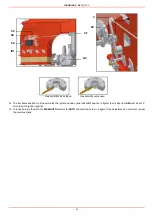
Page 31: ...vocontrol moves the adjusting cam SV to a lower point towards the minimum 11 by measn of a screwdriver turn the cam again to free the microswitch in order that the two bearings meet the screw V to de adju sted screw V to increase the flow rate unscrew to decrease it 12 move again CW refer to figure the AB cam as to press C again the SV adjusting cam moves to the minimum procced as in the prevoius ...

Page 32: ...tion in figure that is why cam AB must be set 5 more than the ignition position 15 Turn the burner off switch the MAN AUTO selector to lAUTO and start the burner up again If the adjustment is not correct repeat the previous steps ID1 VF PA SC SV GV ID2 V SV Gas butterfly valve closed Gas butterfly valve open ...

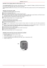
Page 33: ... Refit the transparent plastic cover on the pressure switch Calibration of minimum gas pressure switch As for the gas pressure switch calibration proceed as follows z Remove the transparent plastic cap z While the burner is operating at the maximum output test the gas pressure on the pressure port of the minimum gas pressure switch z Slowly close the manual shut off valve placed upstream the press...

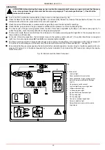
Page 34: ...ANTEES CORRECT AND SAFE FUNCTIONING OF THE BURNER THEREFORE ANY OPERATION OF THE APPLIANCE MUST BE PREVENTED WHICH DEPARTS FROM THE INSTALLATION OPERATIONS OR WHICH HAPPENS AFTER TOTAL OR PARTIAL TAMPERING WITH THESE E G DISCONNECTION EVEN PARTIAL OF THE ELECTRICAL LEADS OPENING THE GENERATOR DOOR DISMANTLING OF PART OF THE BURNER NEVER OPEN OR DISMANTLE ANY COMPONENT OF THE MACHINE OPERATE ONLY T...

Page 35: ...e must appear within 3 seconds after the gas valves opening the transformer is de energized and the light I is turned off The burner is now operating and at the same time the servocontrol moves to the hi flame position 90 see pag 26 z 24 seconds after the gas valves opening the burner starts the automatic operation it works in high or low flame operation for pro gressive PR burners or in the phase...

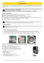
Page 36: ...ween the guides as not to hamper the cap replacement 4 be sure to replace the Or ring into its place C and replace the cover fastening by the proper screws A Inspection and replacement of the MULTIBLOC DUNGS MBC SE filter Threaded valves group WARNING ALL OPERATIONS ON THE BURNER MUST BE CARRIED OUT WITH THE MAINS DISCONNECTED AND THE FUEL MANAUL CUTOFF VALVES CLOSED ATTENTION READ CAREFULLY THE W...

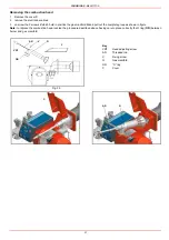
Page 37: ...ition the gas manifold G and pull out the complete group as shown in figure Note to replace the combustion head reverse the procedure described above having care to place correctly the O ring OR between burner and gas manifold Fig 36 Key VRT Head adjusting screw AR Threaded rod V Fixing screw G Gas manifold OR O ring C Cover V C G AR OR VRT C AR G ...

Page 38: ...utside and remove the combustion head D 6 loose the screw of th eignition electrodes support E 7 remove the electrodes and replace them paying attention to the measures showed in figure F G ATTENTION avoid the ignition and detection electrodes to contact metallic parts blast tube head etc otherwise the boi ler s operation would be compromised Check the electrodes position after any intervention on...

Page 39: ...the signal is less than the value indicated check the position of the detection electrode or detector the electrical contacts and if necessary replace the electrode or the detector ATTENTION avoid the ignition and detection electrodes to contact metallic parts blast tube head etc otherwise the boiler s operation would be compromised Check the electrodes position after any intervention on the combu...

Page 40: ...ons according to the laws in force in your country about the Disposal of materials To check the detection signal remove the bridge on TEST ER or TEST FC and connect a micro ammeter when Fig 40 If the signal is less than the value indicated check the position of the detection electrode or detector the electrical con tacts and if necessary replace the electrode or the UV detector Fig 40 Control box ...

Page 41: ...TCH OPEN LACK OF GAS MAXIMUM GAS PRESSURE SWITCH DEFECTIVE THERMOSTATS PRESSURE SWITCHES DEFECTIVES OVERLOAD TRIPPED INTERVENTION AUXILIARIES FUSE INTERRUPTED DEFECTIVE FLAME MONITOR DEVICE DEFECTIVE SERVO CONTROL AIR PRESSURE SWITCH FAULT OR BAD SETTING MINIMUM GAS PRESSURE SWITCH DEFECTIVE OR GAS FILTER DIRTY IGNITION TRANSFORMER FAULT IGNITION ELECTRODES BAD POSITION DETECTION ELECTRODE BAD POS...

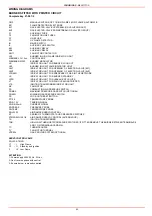
Page 42: ... THE NETWORK LS INDICATOR LIGHT FOR BURNER STAND BY LSPG INDICATOR LIGHT FOR LEAKAGE OF VALVES LT INDICATOR LIGHT FOR FAN OVERLOAD TRIPPED LTA IGNITION TRANSFORMER INDICATOR LIGHT MV FAN MOTOR PA COMBUSTION AIR PRESSURE SWITCH PGMAX MAXIMUM PRESSURE GAS SWITCH OPTIONAL PGMIN MINIMUM GAS PRESSURE SWITCH PS LOCK OUT RESET BUTTON PT100 TEMPERATURE PROBE SD 0 10V TENSION SIGNAL SD 0 4 20mA CURRENT SIG...

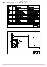
Page 43: ...CIB UNIGAS M039177CA 43 Wiring diagram 21 001 2 Progressive burners ...

Page 44: ...CIB UNIGAS M039177CA 44 Wiring diagram 21 001 2 Fully modulating burners ...

Page 45: ...CIB UNIGAS M039177CA 45 Wiring diagram 21 001 2 WIRING DIAGRAM Cod 09 313 Rev 1 Burners type TP525A Mod M PR x xx x 1 xx ...

Page 46: ...CIB UNIGAS M039177CA 46 ...

Page 47: ...CIB UNIGAS M039177CA 47 ...

Page 48: ...CIB UNIGAS M039177CA 48 ...

Page 49: ...CIB UNIGAS M039177CA 49 WIRING DIAGRAM Cod 09 315 1 Burners type TP525A Mod M MD x xx x 1 xx ...

Page 50: ...CIB UNIGAS M039177CA 50 ...

Page 51: ...CIB UNIGAS M039177CA 51 ...

Page 52: ...CIB UNIGAS M039177CA 52 ...

Page 53: ...60065 2160065 2160065 MINIMUM GAS PRESSURE SWITCH Rp2 2160086 2160086 2160086 2160086 MINIMUM GAS PRESSURE SWITCH DN65 2160076 2160076 2160076 2160076 MINIMUM GAS PRESSURE SWITCH DN80 2160076 2160076 2160076 2160076 MINIMUM GAS PRESSURE SWITCH DN100 2160076 2160076 2160076 2160076 MOTOR 2180276 2180276 2180277 2180206 GAS PROVING SYSTEM 2191604 2191604 2191604 2191604 IGNITION TRANSFORMER 2170302 ...

Page 54: ...065 2160065 2160065 MINIMUM GAS PRESSURE SWITCH Rp2 2160087 2160087 2160087 2160087 MINIMUM GAS PRESSURE SWITCH DN65 2160077 2160077 2160089 2160089 MINIMUM GAS PRESSURE SWITCH DN80 2160077 2160077 2160077 2160077 MINIMUM GAS PRESSURE SWITCH DN100 2160076 2160076 2160076 2160077 MOTOR 2180298 2180209 2180278 2180289 GAS PROVING SYSTEM 2191604 2191604 2191604 2191604 IGNITION TRANSFORMER 2170302 21...

Page 55: ...CIB UNIGAS M039177CA 55 ...

Page 56: ......

Reviews: