background image

Installation
Operation
Maintenance

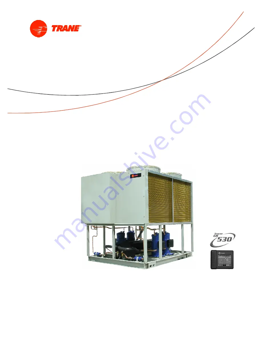
Air-Cooled Condenser
Scroll Compressor
20 to 150 TR

50 / 60 Hz

CGAD-SVN02C-EN

November 2015

SAFETY WARNING
Only qualified personnel should install and service the equipment. The installation, starting up, and servicing of
heating, ventilating, and air-conditioning equipment can be hazardous and requires specific knowledge and
training. Improperly installed, adjusted or altered equipment by an unqualified person could result in death or
serious injury. When working on the equipment, observe all precautions in the literature and on the tags,
stickers, and labels that are attached to the equipment.

Models: 50 or 60 Hz
CGAD020

CGAD040

CGAD025

CGAD050

CGAD030

CGAD060

CGAD070

CGAD100

CGAD080

CGAD120

CGAD090

CGAD150

Summary of Contents for CGAD020

Page 1: ...g and air conditioning equipment can be hazardous and requires specific knowledge and training Improperly installed adjusted or altered equipment by an unqualified person could result in death or seri...

Page 2: ...Use approved and safe cylinders Comply with all the applicable safety and transportation norms when transporting the refrigerant containers In order to minimize emissions when transferring the refrige...

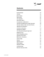
Page 3: ...learance between Units and sound Pressure 10 Application Considerations 11 Checklist for Initial Start 16 Operational Conditions 17 Calculating Subcooling and Superheat 19 Refrigeration Cycle 20 Table...

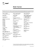
Page 4: ...6 7 8 9 10 11 12 13 14 15 16 17 18 19 20 21 22 23 24 25 26 27 28 29 30 31 32 33 Digit 15 Evaporator Application N Standard Cooling 40 60 F Digit 16 Coil Type A Aluminium fins S Yellow Fin Digit 17 Pi...

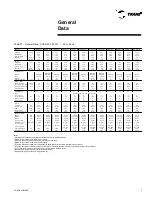
Page 5: ...oll Scroll Scroll Quantity 2 1 1 2 4 2 2 4 2 4 4 2 6 4 6 6 Nominal Capacity Tons 10 15 10 15 15 10 15 10 15 15 10 15 10 15 25 20 25 Water Storage Liters 44 41 62 52 79 143 151 143 122 122 173 277 M in...

Page 6: ...nces recommended for routine maintenance and services see page 12 of this manual The same distances apply in case of various units together Provide the electrical installation The units are designed s...

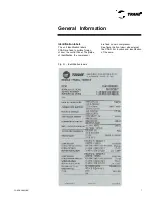
Page 7: ...tification labels CGAD are fixed in surface foreign of door the control Panel The plates of identification the compressor are fixed on own compressor See figure the front view side external the CGAD F...

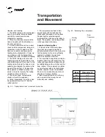
Page 8: ...sition 7 The compressors are fixed to their support tracks with the bolts from the rubber pads themselves and they leave the plant tight for protection against movements that could cause the tubing to...

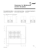
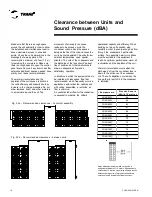
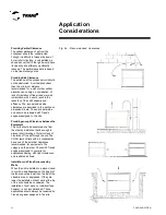
Page 9: ...leave enough room between the units and between the Fig 04 Maintenance and Air Circulation Clearances NOTE Unit mm units and the walls in order to allow a good air circulation without the danger of h...

Page 10: ...may provide diferents results because the large size of equipment and different sources of noise located in defferent positions movement of air supply can cause residues to be sucked up into the conde...

Page 11: ...s should also be insulated Sleeves for the passing of tubes through walls and king posts of insulated tubing with rubber can be used to reduce the noise transmitted by the water tubing In order to red...

Page 12: ...h Trane s engineer assigned to the site Providing enough Clearance between the Equipment The units should be separated one from the other by a distance that is enough to prevent short circuiting of ho...

Page 13: ...result in excessive erosion of the tube The evaporator can resist a reduction of up to 50 of the water flow as long as this flow is the same or greater than the minimal requirements Temperature Limits...

Page 14: ...rol sensor is at the water supply outlet This location makes it so that the building serves as a kind of buffer and ensures a slow changeover in the return water temperature If there is not a sufficie...

Page 15: ...of glass or mercury scaling with colored fluid for contrast purposes and to make reading them easier The pressure gauges should be designed with siphons Install slide valves in order to isolate the p...

Page 16: ...rom electric shocks open and lock in place all the circuit breakers and electric disconnects WARNING Inorder toavoid damagingthe compressors do not operate the unit with anyof the access valves of suc...

Page 17: ...on its plate Check the liquid sight glass The flow of refrigerant should be clean Bubbles in the liquid indicate a low charge of refrigerant or excessive loss of pressure on the liquid line A restric...

Page 18: ...lmixture Themaximum percentageofmixtureof mineralandsyntheticoilis5 Forexample foraretrofitoperationofR407C whenthechillerwillbeloadedwith20litersofsyntheticoilwillbe tolerateinthesystem upto1literofm...

Page 19: ...ape in order to keep out the interference of external temperatures Open the valve of the high pressure manometer on the side of the compressor s discharge if the unit has one A more exact reading will...

Page 20: ...000 megohms Electronic leak detector Ammeter pliers Complete manifold Electronic thermometer R 407C refrigerant and Trane Oil 48 Oxy acetylene soldering machine Temperature pressure table of the R 407...

Page 21: ...0 51 1 55 6 1 1 5 15 0 21 1 3 2 0 52 2 56 7 1 2 0 16 7 22 2 3 3 0 53 9 57 8 1 2 5 17 8 23 9 3 4 0 55 0 58 9 1 3 0 18 9 25 0 3 5 0 56 1 60 6 1 3 5 20 6 26 1 3 6 0 57 2 61 7 1 4 0 21 7 27 2 3 7 0 58 9...

Page 22: ...07 Overheating and subcooling adjustmen7 Check the liquid line sight glass Read Checking Operational Conditions If the operational conditions and the liquid sight glass indicate a lack of gas measure...

Page 23: ...shows on the sight glass e Close the charging valve THEOILRECOMMENDEDFORTHE COMPRESSOR IS Trane Oil 48 Liquid Line Solenoid Valve and Filter Dryer The following conditions indicate that there is a cho...

Page 24: ...ge to the suction pressure gauge or to the connection on the tubing at the entrance of the vacuum pump b Close the access valves on the pressure gauges at the instrument panel so that they don t get d...

Page 25: ...tep F f Manually close the service valve of the liquid line in order to do the reclaiming g Carefully observe the suction pressure manometer When the pressure drops to 10 psig remove the jumper from t...

Page 26: ...he pigtails of the pressure gauges Evacuate the compressor Open the compressor valves Motor burnout Motor burnout implies in the formation of acids and the deposit of oxides and waste on parts of the...

Page 27: ...es of condenser water occurs due to a decrease in the flow of water a small difference in temperature between the entering and leaving water and the condensing temperature that is abnormally high The...

Page 28: ...0 volts is not recommendable for motors with insulation less than 600 Volts because because they could damage them Note 1 megohm 1 000 000 ohms The markings in general should be within the range that...

Page 29: ...1 0 0 3 5 0 0 1 8 8 4 6 1 0 1 9 2 0 2 0 0 0 T o t a l 2 8 3 0 1 7 1 5 C o m p re s s o r e s 2 7 7 6 1 7 1 5 C G A D 0 9 0 F a n s 8 3 2 8 8 8 9 0 3 3 0 0 4 0 0 0 1 8 8 5 5 0 0 2 1 0 0 2 2 5 0 T o t...

Page 30: ...ircuit s protective disconnect that supplies energy to the power terminals 2 3 Turn on the phasemeter at the outlet of the disconnect 2 4 Turn on the electric energy by closing the disconnect 2 5 Read...

Page 31: ...ree voltages measured on a line are 221 volts 230 volts and 227 volts the arithmetic average would be 221 230 227 3 226 V The percentage of unbalance is then 100 x 226 221 226 2 2 The result indicates...

Page 32: ...such as is the case with the reference level of the leaving water The level can be made higher or lower by clicking on the increase or decrease signs Action buttons The actions button come up on a tem...

Page 33: ...tional action is needed to erase the active diagnostic The folder tabs on the top part of the screen are used to select the different types of screens Displacement arrows are added if more tabs option...

Page 34: ...tch the equipment will be informed about the existence of water flow in the evaporator Water Pump Control The controller has an outlet to carry out the actuation of the water pump contactor of the eva...

Page 35: ...led connector system easier connection for factory and field repeated manual disconnection and re connection allowed Figure 14 Conector Acopl vel 24Vcc red wire Terra blk IPC blue IPC gray IPC gray IP...

Page 36: ...CGAD SVN02C EN 36 Wiring Diagram Fig 17 Power and command wiring diagram CGAD 020C Sheet 1 2...

Page 37: ...CGAD SVN02C EN 37 Wiring Diagram Fig 18 Power and command wiring diagram CGAD 020C Sheet 2 2 Part I...

Page 38: ...CGAD SVN02C EN 38 Fig 19 Power and command wiring diagram CGAD 020C Sheet 2 2 Part II Wiring Diagram...

Page 39: ...CGAD SVN02C EN 39 Wiring Diagram V A 1 00 Hz5 0 60 IT AL LUX PATENTEADO ISOL A O V 2500 L2 L3 L1 Fig 20 Layout CGAD 020C...

Page 40: ...CGAD SVN02C EN 40 Wiring Diagram Fig 21 Power and command wiring diagram CGAD025C CGAD030C Sheet 1 2...

Page 41: ...CGAD SVN02C EN 41 Wiring Diagram Fig 22 Power and command wiring diagram CGAD 025C CGAD030C Sheet 2 2 Part I...

Page 42: ...CGAD SVN02C EN 42 Wiring Diagram Fig 23 Power and command wiring diagram CGAD 025C CGAD030C Sheet 2 2 Part II...

Page 43: ...CGAD SVN02C EN 43 Wiring Diagram Fig 24 Layout CGAD 025C CGAD030C V A 10 0 Hz 5 0 60 IT AL LUX PATENT EADO ISOLA O V 2500 L1 L2 L3...

Page 44: ...CGAD SVN02C EN 44 Wiring Diagram Fig 25 Power and command wiring diagram CGAD040C Sheet 1 2 Part I...

Page 45: ...CGAD SVN02C EN 45 Wiring Diagram Fig 26 Power and command wiring diagram CGAD040C Sheet 2 2 Part I...

Page 46: ...CGAD SVN02C EN 46 Fig 27 Power and command wiring diagram CGAD040C Sheet 2 2 Part II Wiring Diagram...

Page 47: ...CGAD SVN02C EN 47 Fig 28 Layout CGAD040C V A 100 Hz 50 60 ITALLUX PATENTEADO ISOL A O V 2500 L1 L2 L3 Wiring Diagram...

Page 48: ...CGAD SVN02C EN 48 Wiring Diagram Fig 29 Power and command wiring diagram CGAD 050C CGAD060C Sheet 1 2...

Page 49: ...CGAD SVN02C EN 49 Wiring Diagram Fig 30 Power and command wiring diagram CGAD 050C CGAD060C Sheet 2 2 Part I...

Page 50: ...CGAD SVN02C EN 50 Fig 31 Power and command wiring diagram CGAD 050C CGAD060C Sheet 2 2 Part II Wiring Diagram...

Page 51: ...CGAD SVN02C EN 51 Wiring Diagram Fig 32 Layout CGAD 050C CGAD060C PATENTEADO ISOL A O V 2500 L1 L2 L3...

Page 52: ...CGAD SVN02C EN 52 Wiring Diagram Fig 33 Power and command wiring diagram CGAD 070C Sheet 1 2...

Page 53: ...CGAD SVN02C EN 53 Wiring Diagram Fig 34 Power and command wiring diagram CGAD 070C Sheet 2 2 Part I...

Page 54: ...CGAD SVN02C EN 54 Wiring Diagram Fig 35 Power and command wiring diagram CGAD 070C Sheet 2 2 Part II...

Page 55: ...CGAD SVN02C EN 55 Wiring Diagram V A 100 Hz 50 60 ITALLUX PATENTEADO ISOLA O V 2500 L1 L2 L3 Fig 36 Layout CGAD 070C...

Page 56: ...CGAD SVN02C EN 56 Wiring Diagram Fig 37 Power and command wiring diagram CGAD080C CGAD090C Sheet 1 2...

Page 57: ...CGAD SVN02C EN 57 Wiring Diagram Fig 38 Power and command wiring diagram CGAD080C CGAD090C Sheet 2 2 Part I...

Page 58: ...CGAD SVN02C EN 58 Wiring Diagram Fig 39 Power and command wiring diagram CGAD080C CGAD090C Sheet 2 2 Part II...

Page 59: ...CGAD SVN02C EN 59 Fig 40 Layout CGAD080C CGAD090C Wiring Diagram V A 100 Hz 50 60 I TALLUX PATENTEADO ISOL A O V 2500 L1 L2 L3...

Page 60: ...CGAD SVN02C EN 60 Wiring Diagram Fig 41 Power and command wiring diagram CGAD100 Part I...

Page 61: ...CGAD SVN02C EN 61 Wiring Diagram Fig 42 Power and command wiring diagram CGAD100 Part II...

Page 62: ...CGAD SVN02C EN 62 Wiring Diagram Fig 43 Power and command wiring diagram CGAD100 Part III...

Page 63: ...CGAD SVN02C EN 63 Wiring Diagram Fig 44 Layout diagram CGAD100...

Page 64: ...CGAD SVN02C EN 64 Wiring Diagram Fig 45 Power and command wiring diagram CGAD120 Part I...

Page 65: ...CGAD SVN02C EN 65 Wiring Diagram Fig 46 Power and command wiring diagram CGAD120 Part II...

Page 66: ...CGAD SVN02C EN 66 Wiring Diagram Fig 47 Power and command wiring diagram CGAD 120 Part III...

Page 67: ...CGAD SVN02C EN 67 Wiring Diagram Fig 48 Layout diagram CGAD 120...

Page 68: ...CGAD SVN02C EN 68 Wiring Diagram Fig 49 Power and command wiring diagram CGAD150 Part I...

Page 69: ...CGAD SVN02C EN 69 Wiring Diagram Fig 50 Power and command wiring diagram CGAD150 Part II...

Page 70: ...CGAD SVN02C EN 70 Wiring Diagram Fig 51 Power and command wiring diagram CGAD150 Part III...

Page 71: ...CGAD SVN02C EN 71 Fig 52 Layout diagram CGAD150 Wiring Diagram...

Page 72: ...CGAD SVN02C EN 72 Wiring Diagram Fig 53 Layout diagram CGAD 100 125 150 with optionals...

Page 73: ...ent of operationfor the equipment was detected onone or morephases of the three phase power supply Local D9 The controller was reset after receiving a new configurationand installationof a new version...

Page 74: ...l beautomatically reset whenthewater flow is reestablished Remote ED After thepresenceof water flow was established intheevaporator aposterior lack of water flow was detected by theflow switch Remote...

Page 75: ...Remote 5 00E 09 A loss of communication was detected between the controller and the external chilled water setpoint Remote 6B6 A loss of communication was detected between the controller and the tempe...

Page 76: ...roller and the solenoid valve control module Remote 6B6 A loss of communication was detected between the controller and the module for protecting compressor A Remote 6B6 A loss of communication was de...

Page 77: ...alid application but also found a failure during selftest The appropriate application for the equipment model should be loaded again using TechView If the failure persists the controller DynaView must...

Page 78: ...hows that there is no power on the side of the line with the motor s starting 1 No power 1 Check the power source 2 An electrical circuit test shows that there is no power on the side of the line with...

Page 79: ...the defective control 2 Same 2 The differential of the low pressure switch is too narrow 2 Adjust the differential for normal working conditions 3 The valve squeaks when closed There is also a change...

Page 80: ...2 Internal parts of the compressor are broken 2 Change the compressor 3 Suction line is too cold 3 Flood back into the compressor 3 Check and adjust the superheat The valve may be too large or the re...

Page 81: ...6 and 10 C 6 Dirty tubes in the condenser s shell and tube 6 The water leaving the condenser is too cold Small temperature increase through the condenser 6 Clean the condenser tubes 7 Poor operation...

Page 82: ...lass 1 Lack of refrigerant 1 Repair the leak and recharge 2 Compressor kicks into short cycling 2 Little thermal charge in the chiller 2 See item B 3 Change of temperature on the liquid line through t...

Page 83: ...ounterclockwise 1 Change two phases 2 Suction pressure is low 2 Lack of gas and motor overheats 2 Eliminate leaks and charge gas 3 Suction pressure is low 3 Compressor starts repeatedly opening the mo...

Page 84: ...21 249 8 74 4 166 330 8 25 0 13 8 6 0 0 32 89 6 25 0 77 170 6 50 0 122 251 6 75 0 167 332 6 24 4 12 10 4 0 6 33 91 4 25 6 78 172 4 50 6 123 253 4 75 6 168 334 4 23 9 11 12 2 1 1 34 93 2 26 1 79 174 2...

Page 85: ...energy efficient environments Trane offers a broad portfolio of advanced controls and HVAC systems comprehensive building services and parts For more information visit www trane com br Trane has a pol...

Reviews: