4-24
T1960CS/T1960CT
5.
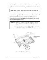
Remove the
M2.5x6 silver screw
from the bottom of the computer (Figure 4-19).
6.
Remove the
two 2.5x10 screws
located next to the power supply circuits on the
lower system board
(Figure 4-19).
7.
Open the PCMCIA expansion slot cover on the right side of the computer, remove
the two M2.5x6 screws securing the cover, then remove the cover.
8.
Lift up the right side of the
lower system board
assembly and slide the assembly
to the right to release the
DC IN jack
on the left side of the board, then lift out the
assembly.
CAUTION:
When you remove the lower system board assembly, carefully slide
the FDD cable out of the hole on the middle frame assembly.
Figure 4-19 Removing the Lower System Board Assembly
9.
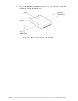
Turn the lower system board assembly over, remove the
two M2.5x8 silver
screws
, then lift off the
lower metal plate
and PCMCIA
ejector button
(Figure
4-20).
Figure 4-20 Removing the Lower Metal Plate
Summary of Contents for T1960CS
Page 20: ...T1960CS T1960CT 2 3 Figure 2 1 Troubleshooting Flowchart 1 2 ...
Page 154: ...B 2 T1960CS T1960CT Figure B 2 FA2SU FA2PU System Board back ...
Page 156: ...B 4 T1960CS T1960CT B 2 FA2SL System Board Figure B 3 FA2SL System Board front ...
Page 157: ...T1960CS T1960CT B 5 Figure B 4 FA2SL System Board back ...
Page 169: ...T1960CS T1960CT D 1 Appendix D USA Display Codes Table D 1 USA Display Codes ...

