4-44
T1960CS/T1960CT
Installing the T1960CT Fluorescent Lamp
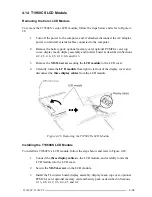
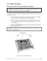
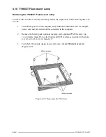
To install the T1960CT’s fluorescent lamp, follow the steps below and refer to Figures 4-36
to 4-38. Note that there are separate grooves for the lamp and its white cable.
1.
Slip the lamp’s
plastic shield
between the lamp and its
white cable
and lay the
lamp into its groove.
2.
Lay the cable into its groove, pressing down gently so that it is held in place by the
small tongues in the groove.
3.
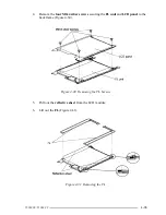
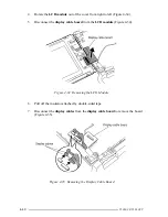
Route the
white
and
blue cables
as shown in Figure 4-38. Make sure the cables
are pressed down snugly so they will not be pinched by other components.
4.
Lay the
metal cover
on the LCD panel making sure the latches marked by circles
in Figure 4-37 fit into their corresponding
notches
on the LCD panel. First, fit the
larger latch
at the center of the edge facing the inverter board into its
notch
,
which should guide the other fittings into position.
5.
Slide the
metal cover
back into place to secure the latches.
6.
Secure the metal cover with
six M2x4 screws
(Figure 4-36).
7.
Install the LCD module, FL inverter board, display mask, top cover, optional
PCMCIA card, optional memory card and battery pack as described in Sections
4.17, 4.16, 4.12, 4.5, 4,4, 4.3 and 4.2.
Summary of Contents for T1960CS
Page 20: ...T1960CS T1960CT 2 3 Figure 2 1 Troubleshooting Flowchart 1 2 ...
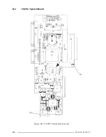
Page 154: ...B 2 T1960CS T1960CT Figure B 2 FA2SU FA2PU System Board back ...
Page 156: ...B 4 T1960CS T1960CT B 2 FA2SL System Board Figure B 3 FA2SL System Board front ...
Page 157: ...T1960CS T1960CT B 5 Figure B 4 FA2SL System Board back ...
Page 169: ...T1960CS T1960CT D 1 Appendix D USA Display Codes Table D 1 USA Display Codes ...

