T1960CS/T1960CT
4-1
4.1
General
This section explains how to disassemble the T1960CS/T1960CT and replace Field Replace-
able Units (FRUs). It may not be necessary to remove all the FRUs in order to replace one.
The chart below is a guide to which FRUs need to be removed in order to remove others.
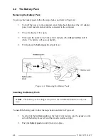
Always start by removing the battery pack,
then follow the chart to determine which FRU you
must remove next in order to repair the one you think is causing the T1960CS/T1960CT to
operate improperly.
❏
Battery Pack
❏
Optional Memory Card
❏
Optional PCMCIA Card
❏
Keyboard
❏
Hard Disk Drive • Backup Battery
❏
Floppy Disk Drive
❏
RTC Battery
❏
STN Color LCD Display (T1960CS)
❏
TFT Color LCD Display (T1960CT)
❏
Upper System Board
❏
Lower System Board
Before You Begin
Look over the procedures in this section before you begin disassembling the T1960CS/
T1960CT. Familiarize yourself with the disassembly and reassembly steps, then begin each
procedure by removing the AC adapter and the battery pack as instructed in Section 4.2,
The
Battery Pack.
1.
Do not disassemble the T1960CS/T1960CT unless it is operating abnormally.
2.
Use only the correct and approved tools.
3.
Make sure the working environment is free from the following elements whether
you are using or storing the T1960CS/T1960CT:
❑
Dust and contaminates
❑
Static electricity
❑
Extreme heat, cold and humidity
4.
Make sure the FRU you are replacing is causing the abnormal operation by per-
forming the necessary diagnostic tests described in this manual.
Summary of Contents for T1960CS
Page 20: ...T1960CS T1960CT 2 3 Figure 2 1 Troubleshooting Flowchart 1 2 ...
Page 154: ...B 2 T1960CS T1960CT Figure B 2 FA2SU FA2PU System Board back ...
Page 156: ...B 4 T1960CS T1960CT B 2 FA2SL System Board Figure B 3 FA2SL System Board front ...
Page 157: ...T1960CS T1960CT B 5 Figure B 4 FA2SL System Board back ...
Page 169: ...T1960CS T1960CT D 1 Appendix D USA Display Codes Table D 1 USA Display Codes ...


