


4-28
T1960CS/T1960CT
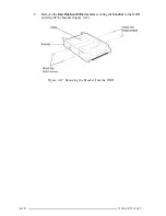
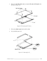
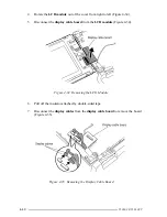
6.
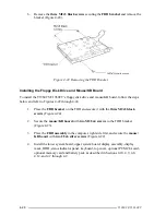
Remove the
three M2x3 black screws
securing the
FDD
bracket
and remove the
bracket (Figure 4-24).
Figure 4-24 Removing the FDD Bracket
Installing the Floppy Disk Drive and Mouse/KB Board
To install the T1960CS/T1960CT’s floppy disk drive and mouse/KB board, follow the steps
below and refer to Figures 4-22 through 4-24.
1.
Place the
FDD bracket
on the FDD and secure it with the
three M2x3 black
screws
(Figure 4-24).
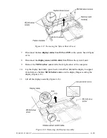
2.
Secure the
mouse/KB board
with
two M2.5x4 screws
to the FDD bracket
(Figure 4-23).
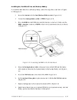
3.
Place the
FDD assembly
in the computer, right side first, and secure the
mouse/
KB board
with
two 2.5x6 silver screws
(Figure 4-22).
4.
Install the lower system board, upper system board, display assembly, display
mask, HDD, status indicator panel, keyboard, top cover, optional PCMCIA card,
optional memory card and battery pack as described in Sections 4.10, 4.9, 4.8,
4.12, and 4.7 through 4.2.
Summary of Contents for T1960CS
Page 20: ...T1960CS T1960CT 2 3 Figure 2 1 Troubleshooting Flowchart 1 2 ...
Page 154: ...B 2 T1960CS T1960CT Figure B 2 FA2SU FA2PU System Board back ...
Page 156: ...B 4 T1960CS T1960CT B 2 FA2SL System Board Figure B 3 FA2SL System Board front ...
Page 157: ...T1960CS T1960CT B 5 Figure B 4 FA2SL System Board back ...
Page 169: ...T1960CS T1960CT D 1 Appendix D USA Display Codes Table D 1 USA Display Codes ...


