IBM ThinkPad 560Z, Supplementary Manual
The IBM ThinkPad 560Z, a top-tier laptop, offers exceptional performance and durability. Easily set up your device with the comprehensive Setup Manual, available for free download from manualshive.com. This user-friendly manual provides step-by-step instructions and ensures a seamless experience with your ThinkPad 560Z.
Share
Download


Reviews:
No comments
Related manuals for ThinkPad 560Z

Aspire 4320
Brand: Acer Pages: 113

Aspire 4240 Series
Brand: Acer Pages: 13

Aspire 4315
Brand: Acer Pages: 106

Aspire 3000 Series
Brand: Acer Pages: 123

Aspire 4743
Brand: Acer Pages: 320

Aspire 1360 Series
Brand: Acer Pages: 104

Aspire 3810T Series
Brand: Acer Pages: 100

Aspire 3050
Brand: Acer Pages: 157

Aspire 3000 Series
Brand: Acer Pages: 84

Aspire 3000 Series
Brand: Acer Pages: 80

Latitude 12 Rugged Extreme 7214
Brand: Dell Pages: 111

Latitude 3189
Brand: Dell Pages: 68

LIFEBOOK E733
Brand: Fujitsu Pages: 32

Latitude 5495
Brand: Dell Pages: 93

Latitude 7200 2-in-1
Brand: Dell Pages: 18

MY8312 Series
Brand: Myria Pages: 48

NB205-N313
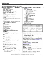
Brand: Toshiba Pages: 4
NB205-N312
Brand: Toshiba Pages: 4


