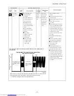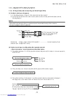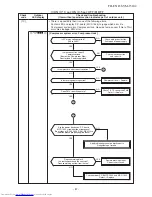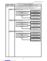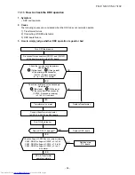
Service Support Function (LED Display, Switch Operation)
1. Outline
A various setup and operation check can be performed by the pushdown button switches (SW01,02)
on the outdoor P.C. board(Display PCB).
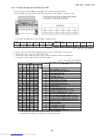
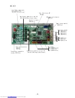
Operation part and Display part on MCC-1646 (Display PCB)
Part No.
Specifications
Operation contents
SW01,02
Pushdown button switch Performs the specific operation to check maintenance and
various initial settings.
D805
Green LED
(1) Power-ON display
When the power of the outdoor unit is turned on, D805
LED goes on.
(2) Error display
When the outdoor controller detects some errors, some
LEDs go on or flash according to the error as described
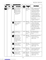
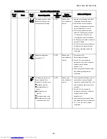
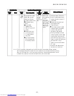
in Error display table. (Refer to ---)
(3) Specific operation display
When SW01 or SW02 is pushed and a specific operation is
operated, some LEDs go on or flash.
D801 to D804
Yellow LED
Display part on MCC-1665(Control PCB)
Part No.
Specifications
Operation contents
D502, D511, D517
Orange LED
Indoor/Outdoor communication (Serial communication)
signal display (Receive signal from indoor signal)
D501, D508, D515
Green LED
Indoor/Outdoor communication (Serial communication)
signal display (Send signal from outdoor signal)
* Every LED is colorless when it goes off.
Control P.C.B MCC-1665
D502,D511,D517 (Orange LED)
:Serial signal (Indoor
→
Outdoor)
D501,D508,D515 (Green LED)
:Serial signal (Outdoor
→
Indoor)
- 8
3
-
FILE NO. SVM-15102
Summary of Contents for RAS-2M14S3AV-E
Page 31: ...4 1 Outdoor Unit 4 CONSTRUCTION VIEWS FILE NO SVM 15102 31 Unit mm ...
Page 116: ......

