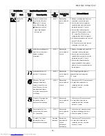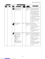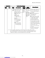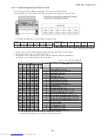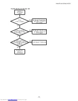
11-6. Trouble Diagnosis by Outdoor LED
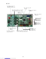
For the outdoor unit, the self-diagnosis is possible by LED (Green) and five LEDs (Yellow).
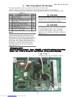
Green LED (D805) and Yellow LEDs (D800 to D804) are provided on the
display
P.C. board MCC-1646.
1. In the initial LED display status, Green LED(D805) is lighted as below.
2. If there is an error, Yellow LED are lighted according to the error as described in the below table.
3. When there are two or more errors, LEDs flash cyclically.
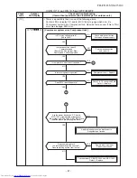
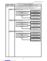
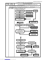
4. When D804 or D805 are flashing (rapid or slow), push and hold SW01 and SW02 simultaneously
for 5 seconds or more. (Display returns to the error display.)
Normal
D800
D801
D802
D803
D804
D805
(Yellow)
(Yellow)
(Yellow)
(Yellow)
(Yellow)
(Green)
●
●
●
●
●
○
○:ON ●:OFF
Error occurring
D800
D801
D802
D803
D804
D805
(Yellow)
(Yellow)
(Yellow)
(Yellow)
(Yellow)
(Green)
●/○*
●/○*
●/○*
●/○*
●/○*
○
○:ON ○*:3 sec ON/0.5 sec OFF ●:OFF
○:ON (○*:3 sec ON/0.5 sec OFF)●:OFF
◎:Rapid Flashing(5 times/sec) ◇:Slow Flashing(1 time/sec)
Display
Indoor
Description
D800 D801 D802 D803 D804 D805 check code
(YL)
(YL)
(YL)
(YL)
(YL)
(GN)
●
●
●
●
●
-
Normal operation (no error)
○*
●
●
●
●
1C
Compressor case thermostat error
●
○*
●
●
●
21
High pressure switch error
○*
○*
●
●
●
1C
Compressor system error
●
●
○*
●
●
1D
Compressor lock
○*
●
○*
●
●
1F
Compressor breakdown
●
○*
○*
●
●
14
Driving element short circuit
○*
○*
○*
●
●
16
Position detection circuit error
●
●
●
○*
●
17
Current detection circuit error
○*
●
●
○*
●
1C
Communication error between MCU
●
○*
●
○*
●
1A
Fan system error
○*
○*
●
○*
●
1E
Discharge temperature error
●
●
○*
○*
●
19
Discharge temperature sensor (TD) error
*1 ○*
●
○*
○*
●
1B
Outdoor air temperature sensor (TO) error
●
○*
○*
○*
●
18
Suction temperature sensor (TS) error
○*
○*
○*
○*
●
18
Heat exchanger temperature sensor (TE) error
*2
●
●
●
●
○*
1C
Gas pipe (unit A) temperature sensor (TGa) error
*2 ○*
●
●
●
○*
1C
Gas pipe (unit B) temperature sensor (TGb) error
*2
●
○*
●
●
○*
1C
Gas pipe (unit C) temperature sensor (TGc) error
○*
●
○*
●
○*
-
PMV error (SH≥20)
●
○*
○*
●
○*
-
PMV error (SH≤–8)
●
●
●
○*
○*
20
PMV leakage error (unit A)
○*
●
●
○*
○*
20
PMV leakage error (unit B)
●
○*
●
○*
○*
20
PMV leakage error (unit C)
○*
●
○*
○*
○*
-
Miswiring (mispiping) check error
∗1: Back-up operation is performed without error display of the indoor unit.
∗2: Operated normally when the air conditioners in other rooms are driven.
○
- 8
4
-
FILE NO. SVM-15102
Summary of Contents for RAS-2M14S3AV-E
Page 31: ...4 1 Outdoor Unit 4 CONSTRUCTION VIEWS FILE NO SVM 15102 31 Unit mm ...
Page 116: ......


