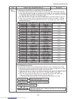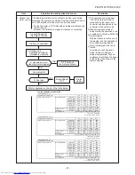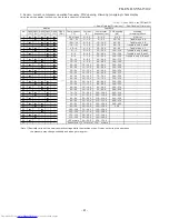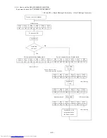
9-3. Intermittent Operation Control for Indoor Fans of the Indoor Unit at Thermo-off
Side in Heating Operation
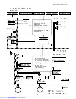
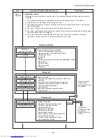
While heating operation is executed in two rooms, if room temperature reached the setup temperature in one
room and thermo-off occurred, the following operations start. (Refer to the figure below.)
1. The indoor unit of the room (A room) in which thermo-off did not occur starts a continuous operation with
the setup number of revolution.
2. The indoor unit of the room (B room) in which thermo-off occurred starts intermittent operation of the indoor fan.
The indoor fan operates with number of revolution of UL or SUL. Fan-ON time is 2 minutes and Fan-OFF
time is 2 to 4 minutes.
However if temperature of the indoor heat exchanger becomes over 55°C or more in B room, the indoor fan
stops the intermittent operation and starts continuous operation.
While heating operation is executed in 2 rooms, if room temperature reached the setup temperature in both
rooms and thermo-off occurred, both indoor units start intermittent operation of the indoor fan.
T on=2 min.
A room
Thermo-ON continues
0 rpm
0 rpm
B room thermo-ON
↓
Thermo-OFF
↓
Thermo-ON
Indoor fan: Operates with setup number of revolution
B room thermo-OFF
B room thermo-ON
Operated with setup number
of revolution
∗
1 Operated with UL or SUL
Fan stop
T off
T off
T off
T on
T on
T on
UL
(
∗
1)
UL
(
∗
1)
UL
(
∗
1)
Fan stop
Fan stop
∗
In case which Tc sensor temperature exceeds 55˚C
in B room, the fan stops intermittent operation and
starts continuous operation with UL or SUL (
∗
1).
2 min.
3 min.
4 min.
To < 5˚C
5 < To < 10
10 < To
T off time
9-4. Service switch (SW01, SW02) operations
Various displays and various operations are enabled by push buttons (service) switches and LED on the
outdoor control P.C. board.
9-4-1. LED display
5 patterns are provided for LED display.
○:ON (○*:3 sec ON/0.5 sec OFF), ●:OFF, ◎:Rapid Flashing(5 times/sec), ◇:Slow Flashing(1 time/sec)
When the initial status does not appear (in case of flashing of D804 or D805), LED display can be returned to
the initial status by pushing and holding the service switches SW01 and SW02 for 5 seconds or more simultaneously.
D800
D801
D802
D803
D804
D805
(Yellow)
(Yellow)
(Yellow)
(Yellow)
(Yellow)
(Green)
●/○
(*)
/◎ ●/○
(*)
/◎ ●/○
(*)
/◎ ●/○
(*)
/◎
●/○
(*)
/◎/◇
●/○/◎/◇
In the initial status of LED display, D805 is ON as below.
Normal
D800
D801
D802
D803
D804
D805
(Yellow)
(Yellow)
(Yellow)
(Yellow)
(Yellow)
(Green)
●
●
●
●
●
○
○:ON ●:OFF
Error occurring
D800
D801
D802
D803
D804
D805
(Yellow)
(Yellow)
(Yellow)
(Yellow)
(Yellow)
(Green)
●/○*
●/○*
●/○*
●/○*
●/○*
○
○:ON ○*:3 sec ON/0.5 sec OFF ●:OFF
FILE NO. SVM-15102
- 5
6
-
Summary of Contents for RAS-2M14S3AV-E
Page 31: ...4 1 Outdoor Unit 4 CONSTRUCTION VIEWS FILE NO SVM 15102 31 Unit mm ...
Page 116: ......

