*
RAS-2M18S3AV-A only
No. Part name
Procedure
Remarks
⑯
Demand P.C.
board
Never forget to put on the gloves at working time;
otherwise an injury will be caused by the parts etc.
When working, be sure to use the insulate tools and
put on the insulated gloves.
Never disassemble the inverter until 1minute
after the power supply was turned off because
there is a fear that an electric shock may occur.
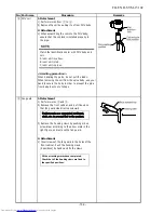
1.Detachment
1) Perform work of
①
and
②
.
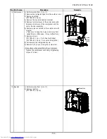
2) Remove the front cover of inverter assembly.
3) Remove the DRC assembly.
(ST1TØ4×10L 1pc.)
4) Remove the cover under inverter box.
(ST1TØ4×6L 2pcs.)
5) Remove the connector of the Demand P.C. board.
CN100 : Power supply (3P, White)
CN101 : Step
‐
down transformer (3P, Yellow)
CN102 : AC17V supply (2P, White)
CN105 : DRC signal output (2P, White)
COM terminal: Red lead wire
DRM1 terminal: White lead wire
DRM2 terminal: Black lead wire
DRM3 terminal: Blue lead wire
These connectors have the lock. The lock must be
released before they are disconnected.
6) Remove the black color lead wire.
(ST2TØ4×8L 1pc.)
7) Remove the Demand P.C. board from the fixture.
8) Exchange the Demand P.C. board with a new one.
Using the bundling band being on the market, be
sure to bind the position which was bound.
- 10
9
-
FILE NO. SVM-15102
Cover under inverter box
Summary of Contents for RAS-2M14S3AV-E
Page 31: ...4 1 Outdoor Unit 4 CONSTRUCTION VIEWS FILE NO SVM 15102 31 Unit mm ...
Page 116: ......

