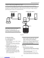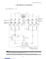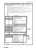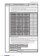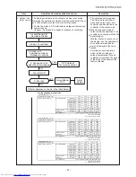
Packed valve
(Gas side)
(dia.9,52)
Pressure
measurement
P
Gauge attaching port
connecting port
Packed valve
(Liquid side)
(dia.6,35)
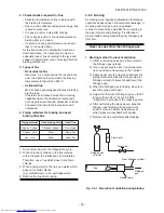
Sectional shape
of heat insulator
Connecting pipe
Thickness : 0,8mm
dia.12,7
Connecting pipe
Thickness : 0,8mm
dia.9,52
Packed valve
(Gas side)
(dia.9,52)
Packed valve
(Gas side)
(dia.12,7)
Connecting pipe
Thickness : 0,8mm
dia.6,35
Packed valve
(Liquid side)
(dia.6,35)
Packed valve
(Liquid side)
(dia.6,35)
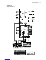
Outdoor unit
Refrigerant amount : 1,50kg (R410A)
TE
TO
Propeller fan
T2
Temp.measurement
TD
Compressor
DA136A1T-40N
High pressure
switch
TS
Accumlating
tank 750cc
TGa
TGb
TGc
To
C room
To
B room
To
C room
To
B room
Pulse motor valve
at liquid side
(dia.1,6)
Al
lo
wa
bl
e
hei
g
ht
di
ffe
re
nc
e
:
1
5
m
A
llo
w
ab
le
pi
pe
l
en
gt
h
Cross flow fan
TA
Indoor unit A
T1
Temp. measurement
TC
Evaporator
・RAS-3M18S3AV-E
, -TR
NOTE :
Gas leak check position
Refrigerant flow (Cooling)
Refrigerant flow (Heating)
7. REFRIGERANT CYCLE DIAGRAM
NOTE :
• You need not add refrigerant if the piping length is
50
m or less.
• Connection of only one indoor unit is unavailable. Two or more indoor units should be connected.
FILE NO. SVM-15102
- 3
6
-
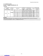
Per 1 unit
Max. : 25m
Min. : 2m
Total
Max. : 50m
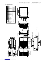
Summary of Contents for RAS-2M14S3AV-E
Page 31: ...4 1 Outdoor Unit 4 CONSTRUCTION VIEWS FILE NO SVM 15102 31 Unit mm ...
Page 116: ......


