background image

<

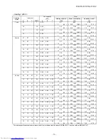
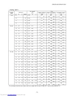
 Heating / 230V >

Unit capacity

Total

(kW)

Heating capacity

Power consumption

Operating current

A

B

C

Σ

kBTU

A

B

C

(kW)

(W)

(A)

1 unit

07

-

-

7

2.70

-

-

2.7

620

3.20

(

1.0

-

4.9

) (

190

-

1640 ) (

1.08

-

7.48

)

10

-

-

10

4.00

-

-

4.0

1120

5.17

(

1.0

-

5.0

) (

190

-

1610 ) (

1.08

-

7.35

)

13

-

-

13

5.00

-

-

5.0

1540

7.04

(

1.0

-

5.5

) (

190

-

1830 ) (

1.08

-

8.32

)

16

-

-

16

5.50

-

-

5.5

1660

7.57

(

1.1

-

6.6

) (

210

-

2320 ) (

1.19

-

10.50 )

2 units

07

07

-

14

2.70

2.70

-

5.4

1370

6.29

(

1.3

-

7.2

) (

240

-

2240 ) (

1.36

-

10.14 )

10

07

-

17

3.22

2.38

-

5.6

1390

6.37

(

1.3

-

7.2

) (

250

-

2200 ) (

1.42

-

9.96

)

13

07

-

20

3.64

1.96

-

5.6

1340

6.15

(

1.3

-

7.5

) (

250

-

2250 ) (

1.42

-

10.18 )

16

07

-

23

3.88

1.72

-

5.6

1240

5.71

(

1.3

-

7.5

) (

240

-

2090 ) (

1.36

-

9.47

)

10

10

-

20

2.80

2.80

-

5.6

1350

6.20

(

1.3

-

7.3

) (

250

-

2160 ) (

1.42

-

9.78

)

13

10

-

23

3.24

2.36

-

5.6

1320

6.06

(

1.3

-

7.5

) (

250

-

2210 ) (

1.42

-

10.01 )

16

10

-

26

3.50

2.10

-

5.6

1220

5.62

(

1.3

-

7.5

) (

240

-

2070 ) (

1.36

-

9.38

)

13

13

-

26

2.80

2.80

-

5.6

1290

5.93

(

1.3

-

7.5

) (

250

-

2170 ) (

1.42

-

9.83

)

16

13

-

29

3.07

2.53

-

5.6

1190

5.48

(

1.3

-

7.5

) (

240

-

2020 ) (

1.36

-

9.16

)

16

16

-

32

2.80

2.80

-

5.6

1140

5.26

(

1.3

-

7.5

) (

240

-

1910 ) (

1.36

-

8.68

)

The above specification values are those under the conditions that the indoor DB/WB=20/-

 and the outdoor DB/WB=7/6

.

<

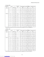
 Heating / 240V >

Unit capacity

Total

(kW)

Heating capacity

Power consumption

Operating current

A

B

C

Σ

kBTU

A

B

C

(kW)

(W)

(A)

1 unit

07

-

-

7

2.70

-

-

2.7

620

3.07

(

1.0

-

4.9

) (

190

-

1640 ) (

1.04

-

7.17

)

10

-

-

10

4.00

-

-

4.0

1120

4.96

(

1.0

-

5.0

) (

190

-

1610 ) (

1.04

-

7.04

)

13

-

-

13

5.00

-

-

5.0

1540

6.75

(

1.0

-

5.5

) (

190

-

1830 ) (

1.04

-

7.98

)

16

-

-

16

5.50

-

-

5.5

1660

7.25

(

1.1

-

6.6

) (

210

-

2320 ) (

1.14

-

10.06 )

2 units

07

07

-

14

2.70

2.70

-

5.4

1370

6.02

(

1.3

-

7.2

) (

240

-

2240 ) (

1.30

-

9.72

)

10

07

-

17

3.22

2.38

-

5.6

1390

6.11

(

1.3

-

7.2

) (

250

-

2200 ) (

1.36

-

9.55

)

13

07

-

20

3.64

1.96

-

5.6

1340

5.90

(

1.3

-

7.5

) (

250

-

2250 ) (

1.36

-

9.76

)

16

07

-

23

3.88

1.72

-

5.6

1240

5.47

(

1.3

-

7.5

) (

240

-

2090 ) (

1.30

-

9.08

)

10

10

-

20

2.80

2.80

-

5.6

1350

5.94

(

1.3

-

7.3

) (

250

-

2160 ) (

1.36

-

9.38

)

13

10

-

23

3.24

2.36

-

5.6

1320

5.81

(

1.3

-

7.5

) (

250

-

2210 ) (

1.36

-

9.59

)

16

10

-

26

3.50

2.10

-

5.6

1220

5.38

(

1.3

-

7.5

) (

240

-

2070 ) (

1.30

-

8.99

)

13

13

-

26

2.80

2.80

-

5.6

1290

5.68

(

1.3

-

7.5

) (

250

-

2170 ) (

1.36

-

9.42

)

16

13

-

29

3.07

2.53

-

5.6

1190

5.26

(

1.3

-

7.5

) (

240

-

2020 ) (

1.30

-

8.78

)

16

16

-

32

2.80

2.80

-

5.6

1140

5.04

(

1.3

-

7.5

) (

240

-

1910 ) (

1.30

-

8.31

)

The above specification values are those under the conditions that the indoor DB/WB=20/-

 and the outdoor DB/WB=7/6

.

Operating 

status

Indoor unit

Operating 

status

Indoor unit

FILE NO. SVM-15102

- 17 -

Summary of Contents for RAS-2M14S3AV-E

Page 1: ...R410A SERVICE MANUAL AIR CONDITIONER SPLIT TYPE RAS 3M18S3AV E TR RAS 2M18S3AV E TR A RAS 2M14S3AV E TR October 2015 FILE NO SVM 15102 ...

Page 2: ... WIRING DIAGRAM 32 6 SPECIFICATIONS OF ELECTRICAL PARTS 35 7 REFRIGERANT CYCLE DIAGRAM 36 8 CONTROL BLOCK DIAGRAM 44 9 OPERATION DESCRIPTION 47 10 INSTALLATION PROCEDURE 64 11 HOW TO DIAGNOSE THE TROUBLE 72 12 HOW TO REPLACE THE MAIN PARTS 100 13 EXPLODED VIEWS AND PARTS LIST 110 FILE NO SVM 15102 2 ...

Page 3: ... conditioner circuit To prevent mixing of refrigerant or refrigerating machine oil the sizes of connecting sections of charging port on main unit and installation tools are different from those used for the conventional refrigerant units Accordingly special tools are required for the new refrigerant R410A units For connecting pipes use new and clean piping materials with high pressure fittings mad...

Page 4: ...CUIT IF AIR OR ANY OTHER GAS IS MIXED IN THE REFRIGERANT THE GAS PRESSURE IN THE REFRIGERATION CIRCUIT WILL BECOME ABNORMALLY HIGH AND IT MAY RESULT IN THE PIPE BURSTING AND POSSIBLE PERSONNEL INJURIES IN THE EVENT THAT THE REFRIGERANT GAS LEAKS OUT OF THE PIPE DURING THE SERVICE WORK AND THE INSTALLATION WORK IMMEDIATELY LET FRESH AIR INTO THE ROOM IF THE REFRIGERANT GAS IS HEATED SUCH AS BY FIRE...

Page 5: ...pe Name of refirigerant R410A Weight of refigerant kg 1 50 Air flow rate Cooling Heating m h 2177 2107 Type Flare connection Outdoor unit Dimension Height mm 630 Width mm 800 Depth Twin rotary type with DC inverter variable speed control Model DA136A1T 40N Fan motor output W 43 mm 300 Net weight kg 46 Compressor Motor output COP COP Cooling Heati 4 44 4 30 Operating noise Outdoor Cooling Heating S...

Page 6: ...pacity Cooling Capacity range Heating Capacity Heating Capacity range Power supply RAS 2M18S3AV E A TR For performance when each indoor unit is combined with other unit refer to the separate table The specifications may be subject to change without notice for purpose of improvement Accessory Outdoor unit Installation manual 1 Wiring connection Power supply interconnection 3 Wires includes earth 4 ...

Page 7: ...nd B unit Connecting These models supports DRM1 DRM2 DRM3 1 E30m total electrical energy kWh used by the air conditioner for all purposes including compressors controls and fans over a 30 min period 2 R rated input electrical power of the air conditioner kW at rated capacity in the mode in which it is operating during the demand response event i e cooling or heating DRED installation position Outl...

Page 8: ...response P C board MCC 1653 2 Transformer VT 02 AC230 240V 50Hz AC230V 50 60Hz 150mA DRC signal transmission connector CN105 DRC signal reception connector CN01 Transformer input connector CN101 Power supply protection fuse F100 250V 3 15A Power supply input connector CN100 Transformer output connector CN102 DB100 LED indicator D101 FILE NO SVM 15102 8 ...

Page 9: ...1380 6 62 2 4 6 2 390 1930 2 27 9 16 16 16 32 2 60 2 60 5 2 1340 6 43 2 4 6 4 390 1950 2 27 9 26 3 units 07 07 07 21 1 74 1 73 1 73 5 2 1220 5 87 2 4 6 5 400 1950 2 32 9 26 10 07 07 24 2 10 1 55 1 55 5 2 1210 5 83 2 4 6 5 400 1950 2 32 9 26 13 07 07 27 2 50 1 35 1 35 5 2 1200 5 78 2 4 6 5 400 1950 2 32 9 26 16 07 07 30 2 76 1 22 1 22 5 2 1190 5 73 2 4 6 5 400 1950 2 32 9 26 10 10 07 27 1 90 1 90 1...

Page 10: ...2 1340 6 15 2 4 6 4 390 1950 2 17 8 85 3 units 07 07 07 21 1 74 1 73 1 73 5 2 1220 5 62 2 4 6 5 400 1950 2 22 8 85 10 07 07 24 2 10 1 55 1 55 5 2 1210 5 57 2 4 6 5 400 1950 2 22 8 85 13 07 07 27 2 50 1 35 1 35 5 2 1200 5 53 2 4 6 5 400 1950 2 22 8 85 16 07 07 30 2 76 1 22 1 22 5 2 1190 5 48 2 4 6 5 400 1950 2 22 8 85 10 10 07 27 1 90 1 90 1 40 5 2 1200 5 53 2 4 6 5 400 1950 2 22 8 85 13 10 07 30 2...

Page 11: ...2 1340 5 90 2 4 6 4 390 1950 2 08 8 48 3 units 07 07 07 21 1 74 1 73 1 73 5 2 1220 5 38 2 4 6 5 400 1950 2 13 8 48 10 07 07 24 2 10 1 55 1 55 5 2 1210 5 34 2 4 6 5 400 1950 2 13 8 48 13 07 07 27 2 50 1 35 1 35 5 2 1200 5 30 2 4 6 5 400 1950 2 13 8 48 16 07 07 30 2 76 1 22 1 22 5 2 1190 5 26 2 4 6 5 400 1950 2 13 8 48 10 10 07 27 1 90 1 90 1 40 5 2 1200 5 30 2 4 6 5 400 1950 2 13 8 48 13 10 07 30 2...

Page 12: ... 8 1640 7 82 1 9 7 5 350 1960 2 05 9 30 3 units 07 07 07 21 2 26 2 27 2 27 6 8 1700 8 10 1 9 8 0 350 2320 2 05 10 97 10 07 07 24 2 75 2 03 2 03 6 8 1680 8 01 1 9 8 0 350 2290 2 05 10 83 13 07 07 27 3 26 1 77 1 77 6 8 1650 7 87 1 9 8 0 350 2250 2 05 10 65 16 07 07 30 3 61 1 60 1 60 6 8 1600 7 64 1 9 8 0 340 2150 1 99 10 18 10 10 07 27 2 48 2 48 1 84 6 8 1660 7 91 1 9 8 0 350 2260 2 05 10 69 13 10 0...

Page 13: ... 6 8 1640 7 48 1 9 7 5 350 1960 1 96 8 90 3 units 07 07 07 21 2 26 2 27 2 27 6 8 1700 7 75 1 9 8 0 350 2320 1 96 10 50 10 07 07 24 2 75 2 03 2 03 6 8 1680 7 66 1 9 8 0 350 2290 1 96 10 36 13 07 07 27 3 26 1 77 1 77 6 8 1650 7 53 1 9 8 0 350 2250 1 96 10 18 16 07 07 30 3 61 1 60 1 60 6 8 1600 7 30 1 9 8 0 340 2150 1 91 9 74 10 10 07 27 2 48 2 48 1 84 6 8 1660 7 57 1 9 8 0 350 2260 1 96 10 23 13 10 ...

Page 14: ... 6 8 1640 7 17 1 9 7 5 350 1960 1 88 8 53 3 units 07 07 07 21 2 26 2 27 2 27 6 8 1700 7 42 1 9 8 0 350 2320 1 88 10 06 10 07 07 24 2 75 2 03 2 03 6 8 1680 7 34 1 9 8 0 350 2290 1 88 9 93 13 07 07 27 3 26 1 77 1 77 6 8 1650 7 21 1 9 8 0 350 2250 1 88 9 76 16 07 07 30 3 61 1 60 1 60 6 8 1600 7 00 1 9 8 0 340 2150 1 83 9 33 10 10 07 27 2 48 2 48 1 84 6 8 1660 7 25 1 9 8 0 350 2260 1 88 9 80 13 10 07 ...

Page 15: ...ose under the conditions that the indoor DB WB 27 19 and the outdoor DB WB 35 Cooling 230V Unit capacity Total kW Cooling capacity Power consumption Operating current A B C ΣkBTU A B C kW W A 1 unit 07 7 2 00 2 0 400 2 22 1 3 3 0 240 840 1 36 3 91 10 10 2 70 2 7 640 3 24 1 3 3 2 240 860 1 36 4 00 13 13 3 70 3 7 1050 4 86 1 4 4 2 240 1400 1 36 6 42 16 16 4 50 4 5 1330 6 11 1 5 5 0 250 1680 1 42 7 6...

Page 16: ...ions that the indoor DB WB 27 19 and the outdoor DB WB 35 Heating 220V Unit capacity Total kW Heating capacity Power consumption Operating current A B C ΣkBTU A B C kW W A 1 unit 07 7 2 70 2 7 620 3 34 1 0 4 9 190 1640 1 13 7 82 10 10 4 00 4 0 1120 5 41 1 0 5 0 190 1610 1 13 7 68 13 13 5 00 5 0 1540 7 36 1 0 5 5 190 1830 1 13 8 70 16 16 5 50 5 5 1660 7 91 1 1 6 6 210 2320 1 25 10 97 2 units 07 07 ...

Page 17: ...e conditions that the indoor DB WB 20 and the outdoor DB WB 7 6 Heating 240V Unit capacity Total kW Heating capacity Power consumption Operating current A B C ΣkBTU A B C kW W A 1 unit 07 7 2 70 2 7 620 3 07 1 0 4 9 190 1640 1 04 7 17 10 10 4 00 4 0 1120 4 96 1 0 5 0 190 1610 1 04 7 04 13 13 5 00 5 0 1540 6 75 1 0 5 5 190 1830 1 04 7 98 16 16 5 50 5 5 1660 7 25 1 1 6 6 210 2320 1 14 10 06 2 units ...

Page 18: ...1 6 4 5 290 1130 1 64 5 22 10 07 17 2 30 1 70 4 0 870 4 05 1 6 4 6 290 1130 1 64 5 22 13 07 20 2 60 1 40 4 0 850 3 96 1 6 4 7 290 1140 1 64 5 26 10 10 20 2 00 2 00 4 0 850 3 96 1 6 4 7 290 1140 1 64 5 26 13 10 23 2 31 1 69 4 0 840 3 91 1 6 4 8 290 1150 1 64 5 31 13 13 26 2 00 2 00 4 0 830 3 87 1 6 4 9 290 1150 1 64 5 31 Cooling 240V Unit capacity Total kW Cooling capacity Power consumption Operati...

Page 19: ...1270 1 36 5 84 10 07 17 2 53 1 87 4 4 910 4 23 1 3 5 1 250 1250 1 42 5 75 13 07 20 2 86 1 54 4 4 880 4 09 1 3 5 2 250 1250 1 42 5 75 10 10 20 2 20 2 20 4 4 890 4 14 1 3 5 1 250 1230 1 42 5 66 13 10 23 2 54 1 86 4 4 870 4 05 1 3 5 2 250 1230 1 42 5 66 13 13 26 2 20 2 20 4 4 850 3 96 1 3 5 2 250 1220 1 42 5 62 Heating 240V Unit capacity Total kW Heating capacity Power consumption Operating current A...

Page 20: ...flow High Pipe length 5m 2 2 units operating Conditions Indoor DB27Ԩ WB19Ԩ Indoor air flow High Pipe length 5m 2 2 units operating Conditions Indoor DB20Ԩ Indoor air flow High Pipe length 5m 2 2 units operating Conditions Indoor DB27Ԩ WB19Ԩ Indoor air flow High Pipe length 5m 3 3 units operating Conditions Indoor DB20Ԩ Indoor air flow High Pipe length 5m 3 3 units operating 220V 230V 240V 220V 230...

Page 21: ...imited start Conditions Indoor DB27Ԩ WB19Ԩ Indoor air flow High Pipe length 5m 2 2 units operating Conditions Indoor DB27Ԩ WB19Ԩ Indoor air flow High Pipe length 5m 3 3 units operating Current limited start Current limited start Conditions Indoor DB20Ԩ Indoor air flow High Pipe length 5m 2 2 units operating Conditions Indoor DB20Ԩ Indoor air flow High Pipe length 5m 2 2 units operating Conditions ...

Page 22: ...ow High 2 units operating Conditions Indoor DB27Ԩ WB19Ԩ Outdoor DB35Ԩ Indoor air flow High 2 units operating Conditions Indoor DB20Ԩ Outdoor DB7Ԩ DW6Ԩ Indoor air flow High 2 units operating Conditions Indoor DB27Ԩ WB19Ԩ Outdoor DB35Ԩ Indoor air flow High 3 units operating Conditions Indoor DB20Ԩ Outdoor DB7Ԩ DW6Ԩ Indoor air flow High 3 units operating Standard pipe length 15m Standard pipe length ...

Page 23: ...n the refrigeration cycle may become abnormally high so that a rupture or personal injury may be caused 5 After completion of installation work check to make sure that there is no refrigeration gas leakage If the refrigerant gas leaks into the room coming into contact with fire in the fan driven heater space heater etc a poisonous gas may occur 6 When an air conditioning system charged with a larg...

Page 24: ...r or dust does not enter the pipe interior that no other oil than lubricating oils used in the installed air water heat pump is used and that refrigerant does not leak When using lubricating oils in the piping processing use such lubricating oils whose water content has been removed When stored be sure to seal the container with an airtight cap or any other cover 1 Flare processing procedures and ...

Page 25: ...Outer diameter mm 6 35 9 52 12 70 15 88 Thickness mm 0 8 0 8 0 8 1 0 A mm Flare tool for R410A Conventional flare tool clutch type Clutch type Wing nut type 0 to 0 5 1 0 to 1 5 1 5 to 2 0 0 to 0 5 1 0 to 1 5 1 5 to 2 0 0 to 0 5 1 0 to 1 5 2 0 to 2 5 0 to 0 5 1 0 to 1 5 2 0 to 2 5 Nominal diameter 1 4 3 8 1 2 5 8 Outer diameter mm 6 35 9 52 12 70 15 88 Thickness mm 0 8 0 8 0 8 1 0 A mm Flare tool f...

Page 26: ...que for R410A is the same as that for conventional R22 Incidentally when the torque is weak the gas leakage may occur When it is strong the flare nut may crack and may be made non removable When choosing the tightening torque comply with values designated by manufacturers Table 3 2 7 shows reference values NOTE When applying oil to the flare surface be sure to use oil designated by the manufacture...

Page 27: ...ng currently developed General tools Conventional tools can be used In addition to the above exclusive tools the following equipments which serve also for R22 are necessary as the general tools 1 Vacuum pump 7 Screwdriver Use vacuum pump by attaching vacuum pump adapter 8 Spanner or Monkey wrench 2 Torque wrench For Ø6 35 Ø9 52 9 Hole core drill Ø65 3 Pipe cutter 10 Hexagon wrench Opposite side 4m...

Page 28: ...nnecting port of the electronic balance and charge liquid refrigerant Outdoor unit Indoor unit Opened Opened Refrigerant cylinder with siphon Check valve Open close valve for charging Electronic balance for refrigerant charging Opened Closed Service port 3 4 Recharging of Refrigerant When it is necessary to recharge refrigerant charge the specified amount of new refrigerant according to the follow...

Page 29: ...silver and copper It is used to join iron copper or copper alloy and is relatively expensive though it excels in solderability 2 Phosphor bronze brazing filler Phosphor bronze brazing filler is generally used to join copper or copper alloy 3 Low temperature brazing filler Low temperature brazing filler is generally called solder and is an alloy of tin and lead Since it is weak in adhesive strength...

Page 30: ...x which does not contain chlorine 3 When adding water to the flux use water which does not contain chlorine e g distilled water or ion exchange water 4 Remove the flux after brazing 3 5 3 Brazing As brazing work requires sophisticated techniques experiences based upon a theoretical knowledge it must be performed by a person qualified In order to prevent the oxide film from occurring in the pipe in...

Page 31: ...4 1 Outdoor Unit 4 CONSTRUCTION VIEWS FILE NO SVM 15102 31 Unit mm ...

Page 32: ...T POWER SUPPLY F03 250V T3 15A MCC 1645 BOARD MAIN P C COMPRESSOR FAN MOTOR CN700 YEL L F CN802 BLU P05 P04 P06 F01 250V T25A P02 P01 5 5 5 1 CN501 GRN GRN D800 3 3 P22 2 1 3 1 2 3 4 1 2 3 4 1 2 3 2 1 2 1 2 1 3 1 2 1 2 1 2 3 4 6 1 2 3 4 6 BLK WHI CN300 WHI For D800 refer to the installation and service manual COM DRM1 DRM2 DRM3 RED WHI RED BLU BLK WHI CN100 MCC 1653 P C BOARD DEMAND 250V T3 15A F ...

Page 33: ... 4WAY VALVE COIL 4WV WHI CN704 COMPRESSOR THERMOSTAT FOR REACTOR REACTOR CN500 BLU P21 P16 P17 P07 CIRCUIT POWER SUPPLY F03 250V T3 15A MCC 1645 BOARD MAIN P C COMPRESSOR FAN MOTOR CN700 YEL L F CN802 BLU P05 P04 P06 F01 250V T25A P02 P01 5 5 5 1 CN501 GRN GRN D800 3 3 P22 2 1 3 1 2 3 4 1 2 3 4 1 2 3 2 1 2 1 2 1 3 1 2 1 2 1 2 3 4 6 1 2 3 4 6 BLK WHI CN300 WHI For D800 refer to the installation and...

Page 34: ...MV B PMV A SWITCH HIGH PRESSURE BLU CN806 4WAY VALVE COIL 4WV WHI CN704 COMPRESSOR THERMOSTAT FOR REACTOR REACTOR CN500 BLU P21 P16 P17 P07 CIRCUIT POWER SUPPLY F03 250V T3 15A COMPRESSOR FAN MOTOR SW01 SW02 D805 GRN MCC 1646 Display P C Board 2 CN01 WHI 10 10 PMV C M 5 CN700 YEL L F BLK CN02 YEL CN802 BLU P05 P04 P06 2 6 F01 250V T25A P02 P01 5 CN805 WHI 5 5 5 1 CN501 GRN GRN D800 3 3 P22 2 1 3 1...

Page 35: ...6 3A 12 Fuse Mounted on P C board MCC 1645 MCC 1665 AC250V 3 15A 13 Outdoor temp sensor TO sensor 10kΩ 25 14 Evaporator temp sensor Te sensor 10kΩ 25 15 Discharge temp sensor Td sensor 50kΩ 25 16 Suction temp sensor Ts sensor 10kΩ 25 17 Temp sensor at A room gas side TGA sensor 10kΩ 25 18 Temp sensor at B room gas side TGB sensor 10kΩ 25 19 Temp sensor at C room gas side TGC sensor only 3M series ...

Page 36: ...peller fan T2 Temp measurement TD Compressor DA136A1T 40N High pressure switch TS Accumlating tank 750cc TGa TGb TGc To C room To B room To C room To B room Pulse motor valve at liquid side dia 1 6 Allowable height difference 15m Allowable pipe length Cross flow fan TA Indoor unit A T1 Temp measurement TC Evaporator RAS 3M18S3AV E TR NOTE Gas leak check position Refrigerant flow Cooling Refrigeran...

Page 37: ...surement TD Compressor DA136A1T 40N High pressure switch TS TGa TGb To B room To B room Pulse motor valve at liquid side dia 1 6 Allowable height difference 15m Allowable pipe length Cross flow fan TA Indoor unit A T1 Temp measurement TC Evaporator RAS 2M18S3AV E A TR RAS 2M14S3AV E TR NOTE Gas leak check position Refrigerant flow Cooling Refrigerant flow Heating NOTE You need not add refrigerant ...

Page 38: ... 19 35 16 13 0 9 to 1 1 12 to 14 45 to 47 High 64 16 16 1 0 to 1 2 14 to 16 45 to 47 High 62 3 units 07 07 07 1 0 to 1 2 14 to 16 45 to 47 High 60 10 07 07 1 0 to 1 2 14 to 16 45 to 47 High 60 13 07 07 1 0 to 1 2 15 to 17 45 to 47 High 60 16 07 07 1 1 to 1 3 16 to 18 45 to 47 High 59 10 10 07 1 0 to 1 2 15 to 17 45 to 47 High 60 13 10 07 1 0 to 1 2 15 to 17 45 to 47 High 60 16 10 07 1 1 to 1 3 16 ...

Page 39: ... 91 20 7 6 16 13 2 3 to 2 5 39 to 41 1 to 1 High 90 16 16 2 1 to 2 3 37 to 39 1 to 1 High 90 3 units 07 07 07 2 1 to 2 3 36 to 38 1 to 1 High 93 10 07 07 2 1 to 2 3 35 to 37 1 to 1 High 93 13 07 07 2 0 to 2 2 35 to 37 1 to 1 High 93 16 07 07 1 9 to 2 1 33 to 35 1 to 1 High 93 10 10 07 2 0 to 2 2 35 to 37 1 to 1 High 93 13 10 07 2 0 to 2 2 34 to 36 1 to 1 High 93 16 10 07 1 9 to 2 1 33 to 35 1 to 1...

Page 40: ...o 14 43 to 45 High 48 10 07 0 8 to 1 0 10 to 12 45 to 47 High 62 27 19 35 13 07 0 8 to 1 0 10 to 12 46 to 48 High 70 16 07 0 9 to 1 1 12 to 14 45 to 47 High 66 10 10 0 8 to 1 0 10 to 12 46 to 48 High 71 13 10 0 8 to 1 0 10 to 12 46 to 48 High 69 16 10 0 9 to 1 1 12 to 14 45 to 47 High 65 13 13 0 8 to 1 0 11 to 13 46 to 48 High 68 16 13 0 9 to 1 1 12 to 14 45 to 47 High 64 16 16 1 0 to 1 2 14 to 16...

Page 41: ... 2 6 40 to 42 0 to 2 High 71 10 07 2 4 to 2 6 40 to 42 0 to 2 High 74 20 7 6 13 07 2 3 to 2 5 38 to 40 0 to 2 High 73 16 07 2 1 to 2 3 35 to 37 0 to 2 High 72 10 10 2 3 to 2 5 39 to 41 0 to 2 High 73 13 10 2 2 to 2 4 37 to 39 0 to 2 High 73 16 10 2 1 to 2 3 35 to 37 0 to 2 High 72 13 13 2 2 to 2 4 36 to 38 0 to 2 High 73 16 13 2 0 to 2 2 34 to 36 0 to 2 High 72 16 16 1 9 to 2 1 32 to 34 0 to 2 Hig...

Page 42: ...3 0 7 to 0 9 7 to 9 43 to 45 High 57 2 units 07 07 0 9 to 1 1 12 to 14 43 to 45 High 48 27 19 35 10 07 0 8 to 1 0 10 to 12 45 to 47 High 47 13 07 0 8 to 1 0 10 to 12 46 to 48 High 46 10 10 0 8 to 1 0 10 to 12 46 to 48 High 46 13 10 0 8 to 1 0 10 to 12 46 to 48 High 46 13 13 0 8 to 1 0 11 to 13 46 to 48 High 45 NOTES 1 Measure surface temperature of heat exchanger pipe around of heat exchanger path...

Page 43: ... 55 13 2 9 to 3 1 47 to 49 2 to 4 High 60 2 units 07 07 2 1 to 2 3 35 to 37 2 to 4 High 56 20 7 6 10 07 2 0 to 2 2 34 to 36 2 to 4 High 56 13 07 2 0 to 2 2 33 to 35 2 to 4 High 56 10 10 2 0 to 2 2 34 to 36 2 to 4 High 56 13 10 1 9 to 2 1 33 to 35 1 to 3 High 56 13 13 1 9 to 2 1 32 to 34 1 to 3 High 56 NOTES 1 Measure surface temperature of heat exchanger pipe around of heat exchanger path U bent T...

Page 44: ... Function select MCC 1665 Control P C B MCC 1645 MAIN P C B M C U PWM synthesis function Input current release control IPM over current detect control High power factor correction control Signal Communication with Control P C B Fan motor control Compressor motor control 4 way valve control High pressure switch Case thermo Noise filter Input current Sensor Converter AC DC Inverter DC AC Inverter DC...

Page 45: ...on select MCC 1665 Control P C B MCC 1645 MAIN P C B M C U PWM synthesis function Input current release control IPM over current detect control High power factor correction control Signal Communication with Control P C B Fan motor control Compressor motor control 4 way valve control High pressure switch Case thermo Noise filter Input current Sensor 4 way valve Relay circuit Converter AC DC Inverte...

Page 46: ...MAIN P C B M C U PWM synthesis function Input current release control IPM over current detect control High power factor correction control Signal Communication with Control P C B Fan motor control Compressor motor control 4 way valve control High pressure switch Case thermo Noise filter Input current Sensor 4 way valve Relay circuit Converter AC DC Inverter DC AC Inverter DC AC High power factor c...

Page 47: ...mode set on the remote controller Compressor revolution command signal defined by indoor temperature and set temperature Correction along with variation of room temperature and correction of indoor heat exchanger temperature are added Temperature of indoor heat exchanger For these signals Operation mode and Compressor revolution indoor heat exchanger temperature the outdoor unit controller monitor...

Page 48: ...e control 53 5 Winding Coil heating control 54 6 Defrost control Only in heating operation 54 7 Compressor protective control 54 8 Discharge temperature control 55 9 Pulse motor valve PMV control 55 9 3 Intermittent Operation Control for Indoor Fans of the Indoor Unit at Thermo off Side in Heating Operation 56 10 High pressure switch Compressor case thermostat control 55 9 4 Service switch SW01 SW...

Page 49: ...operation function Compressor Outdoor fan motor 4 way valve Pulse motor valve P M V Signal receiving Indoor unit control Operation command Serial signal send receive Selection of operation conditions ON OFF Serial signal send receive Outdoor unit control Inverter Item 1 Basic operation Operation flow and applicable data etc 1 Operation control Receiving the user s operation condition setup the ope...

Page 50: ... the operation signal sent from the indoor unit 1 The relay of 4 way valve is turned on for a few seconds when 4 way valve is driven Description No 1 2 3 4 5 6 7 8 9 10 11 12 13 14 15 16 Indoor unit Pushed first Pushed last Pushed first Pushed last Pushed first Pushed last Pushed first Pushed last Pushed first Pushed last Pushed first Pushed last Pushed first Pushed last Pushed first Pushed last P...

Page 51: ...r revolution the speed of the outdoor fan shown in the table is selected Cooling operation dry operation RAS 3M18S3AV E TR Compressor revolution rps 20 50 55 56 Outdoor temp sensor To Normal operation To 38 350 630 720 800 28 To 38 350 550 630 720 15 To 28 300 550 550 630 10 To 15 300 470 470 550 5 To 10 300 350 350 470 0 To 5 300 300 300 350 To 0 0 0 300 0 300 0 300 Sleep or quiet To 38 350 550 6...

Page 52: ...20 470 operation 0 To 10 470 470 550 5 To 0 550 550 550 To 5 550 550 550 To is abnormal 550 550 630 Maximum revolution To Outdoor temp sensor Indoor unit A Inverter Outdoor unit Compressor Indoor unit B Indoor unit C 3 Capacity control 1 Four indoor units from A to E determine the respective instruction revolutions from the difference between the remote controller setting temperature Ts and the in...

Page 53: ...d from the indoor unit within the range which does not exceed the specified value Outdoor temp 10 5 A 11 5 A 11 5 A 11 5 A 16 C 11 C 15 5 C 10 5 C Cooling current release value Heating current release value 8 5 A 45 C 40 C 44 C 39 C 8 5 A RAS 2M18S3AV E TR A Operation No of Compressor Operation No of Compressor mode operating revolution mode operating revolution unit Combination of indoor units kB...

Page 54: ...ntinue Description Winding Coil heating is performed when the following conditions are met Condition 1 When the discharge sensor temperature Td is less than 30 C Condition 2 When the outdoor sensor temperature To is as shown in the left figure The necessity of defrost operation is detected by the outdoor heat exchanger temperature The conditions to detect the necessity of defrost operation differ ...

Page 55: ...nt SH control 3 If the discharge temperature was excessively up adjust the open degree of valve so that it is in the range of set temperature Discharge temp control 4 When defrost operation is performed the open degree of PMV is adjusted according to each setup conditions during preparation for defrost and during defrost operation 4 way valve is inversed 5 When turning off the compressor by thermo...

Page 56: ...rmo OFF Thermo ON Indoor fan Operates with setup number of revolution B room thermo OFF B room thermo ON Operated with setup number of revolution 1 Operated with UL or SUL Fan stop T off T off T off T on T on T on UL 1 UL 1 UL 1 Fan stop Fan stop In case which Tc sensor temperature exceeds 55 C in B room the fan stops intermittent operation and starts continuous operation with UL or SUL 1 2 min 3 ...

Page 57: ...e validated 6 When you want to continue the settings moreover repeat items from 3 to 5 7 To invalidate various settings execute items 1 to 3 push SW02 and then D805 will turn off 8 Push and hold SW02 for 5 seconds or more D804 changes to slow flashing D805 is turned off and then various settings are invalidated If an unknown point generated on the way of the operation push and hold SW01 and SW02 f...

Page 58: ...all indoor units During the check the display is kept as below Operation is up to 30 minutes You cannot check wiring piping when the external temperature is 5 or less During the check the compressor and the fun of the outdoor indoor unit repeat ON OFF Operate the fan motor forcedly The motor rotates at 500rpm and operation is 2 minutes During the check the display is kept as below PMV is initializ...

Page 59: ...temperature sensor TS display Outside temperature sensor TO display The detected value of the gas temperature sensor TG is displayed Refer to table C The detected value of the gas temperature sensor TG is displayed Refer to table C The detected value of the gas temperature sensor TG is displayed Refer to table C The detected value of the indoor suction temperature sensor TA is displayed Refer to t...

Page 60: ... sensor TGb error 2 1C Gas pipe unit C temperature sensor TGc error PMV error SH 20 PMV error SH 8 20 PMV leakage error unit A 20 PMV leakage error unit B 20 PMV leakage error unit C Miswiring mispiping check error 1 Back up operation is performed without error display of the indoor unit 2 Operated normally when the air conditioners in other rooms are driven B Error display of the latest error inc...

Page 61: ...nd C 6 0 4 6 6 9 30 34 9 120 139 Trouble in unit B and C 7 5 9 7 7 9 35 39 9 140 159 Trouble in unit A B and C 8 10 14 8 8 9 40 44 9 160 179 9 15 19 9 9 9 45 49 9 180 199 10 20 24 10 10 9 50 54 9 200 219 11 25 29 11 11 9 55 59 9 220 239 12 30 34 12 12 9 60 64 9 240 259 13 35 39 13 13 9 65 69 9 260 279 14 40 44 14 14 9 70 74 9 280 299 15 45 49 15 15 9 75 79 9 300 319 16 50 54 16 16 9 80 84 9 320 33...

Page 62: ...tting display starts Yes No D800 D801 D802 D803 D804 D805 Yellow Yellow Yellow Yellow Yellow Green Initial status Push SW01 02 at the same time for 5 sec or more Turn on the circuit breaker D800 D801 D802 D803 D804 D805 Yellow Yellow Yellow Yellow Yellow Green Push SW02 1 time D800 D801 D802 D803 D804 D805 Yellow Yellow Yellow Yellow Yellow Green Hold time t 5 sec Push SW02 Yes No D800 D801 D802 D...

Page 63: ...play starts Yes No D800 D801 D802 D803 D804 D805 Yellow Yellow Yellow Yellow Yellow Green Push SW01 8 times Initial status Push SW01 02 at the same time for 5 sec or more Turn on the circuit breaker Push SW02 1 time Push SW01 Support function item Compressor operation frequency Item selecting Information display Refer to 9 4 5 Compressor ON D800 D801 D802 D803 D804 D805 Yellow Yellow Yellow Yellow...

Page 64: ...ge manifold Charge hose Electronic balance for refrigerant charging Torque wrench nominal diam 1 2 5 8 Flare tool clutch type Gauge for projection adjustment Vacuum pump adapter Gas leakage detector Applicable to R22 model Changes As pressure is high it is impossible to measure by means of conventional gauge In order to prevent any other refrigerant from being charged each port diameter has been c...

Page 65: ...ene form 6 mm thick When duct type or cassette type unit is to be installed it shall be covered with thicker insulating material Polyetylene form 10 mm thick Parts name Refrigerant piping 1 Putty PVC tapes Parts name Indoor unit abbreviation Liquid side O D Gas side O D 07 10 13 6 35 mm 9 52 mm 16 6 35 mm 12 7 mm Q ty 1 ea 1 ea Rubber cap Water proof Installation manual 1 2 CD ROM Installation man...

Page 66: ...on the inside rather than the outside When using an air conditioner under low outside temperature conditions Outside temp 5 C or lower In COOL mode prepare a duct or wind shield so that it is not affected by the wind Necessary Space for Installation If you need to install the outdoor unit in a location where there are some obstructions or a wall secure sufficient space as shown in the figure below...

Page 67: ...arge hose Make sure that the Handle Hi of the gauge manifold valve is closed fully Connect the port of the gauge manifold valve and the service port Valve core Setting Pin using the charge hose NOTE If a control valve or charge valve is attached to the charge hose leak of R410A refrigerant can be avoided 2 Open the Handle Low of the gauge manifold valve fully then operate the vacuum pump Loosen th...

Page 68: ...required depending on European or local legislation Insulation of the Refrigerant Pipes Insulate the refrigerant pipes for liquid and gas separately Heat proof bubble polyethylene Gas Leak Inspection Perform a gas leak inspection for the flare nut connections valve stem connection and service port cap without fail Use a leak detector exclusively manufactured for R410A Flare nut connections Indoor ...

Page 69: ...ing cable to the terminal as identified by the matching numbers on the terminal block of the indoor and the outdoor unit 5 Fix the wiring connections for the power source and each indoor unit securely using a cord clamp 6 Attach the terminal cover and the valve cover Stripping Length of connecting cable for outdoor unit 55 5 5 30 1 2 3 5 5 30 55 L N Earth wire Earth wire Power cord Connecting cabl...

Page 70: ...a possibility to misjudge if the indoor temperature becomes too low by cooling operation In that case execute the cooling operation for per room and check if the connection is normal Gas Leak Inspection Refer to the Gas Leak Inspection Test run 1 If you perform the test run in summer start running in the cooling mode first to decrease the temperature of the room then run in the heating mode Heatin...

Page 71: ...ng mode The checking procedure cannot be completed if the cooling mode is not operated in every indoor units 4 Hold down SW01 for at least 5 seconds and check that D800 is lighted and D804 light is flashing 1 time sec D800 D801 D802 D803 D804 D805 5 Press SW01 for 1 time Then D804 light is flashing 5 times sec D800 D801 D802 D803 D804 D805 6 Press SW02 for 1 time Then D805 light is flashing 5 time...

Page 72: ... discharge according to error contents and the voltage may remain Therefore be sure to discharge the capacitor WARNING For discharging never use a screwdriver and others for short circuiting between and electrodes As the electrolytic capacitor is one with a large capacity it is very dangerous because a large electric spark will occur Table 11 1 No 1 2 3 4 5 6 7 8 9 Troubleshooting Procedure First ...

Page 73: ...ode the operation mode is changed In HEAT mode the compressor motor speed does not increase up to the maximum speed or decreases before the temperature arrives at the set temperature Cool Dry or Heat operation cannot be performed Description The OPERATION lamp of the indoor unit flashes when power source is turned on If START STOP button is operated once flashing stops Flashes also in power failur...

Page 74: ... contents of items B and C and a part of item E are displayed when air conditioner operates When item B and C and item B and a part of item E occur concurrently priority is given to the block of item B The check codes can be confirmed on the remote controller for servicing Indoor indication lamp flashes Which lamp does flash Item A B C D E Check code Block display OPERATION Green Flashing display ...

Page 75: ... ON or OFF button If there is no fault with a code the indoor unit will beep once Beep and the display of the remote controller will change as follows The TIMER indicator of the indoor unit flashes continuously 5 times per 1 sec Check the unit with all 52 check codes to as shown in Table 11 4 1 Press ON or OFF button to change the check code backward If there is a fault the indoor unit will beep f...

Page 76: ...oom Operation Flashes when 1 Check the sensor TA and connection board temperature sensor is continues error is detected 2 In case of the sensor and its short Circuit or disconnection connection is normal check the P C board TC sensor The heat Operation Flashes when 1 Check the sensor TC and connection exchanger temperature continues error is detected 2 In case of the sensor and its sensor of the i...

Page 77: ...or unit open 4 The outdoor unit abnormal stop at circuit of signal some time Signal circuit of indoor If the other check codes are found P C board or outdoor concurrently check them together P C board is failure Check protector hardware such in some period as Hi Pressure switch Thermal Relay etc Check refrigerant amount or any possibility case which may caused high temperature or high pressure Che...

Page 78: ...resistance of compressor winding If circuit is shortage replace the compressor Current detect circuit of All OFF Flashes after Even if trying to operate again all inverter P C board error error is detected operations stop replace inverter 4 times P C board TE sensor The heat All OFF Flashes after 1 Check sensors TE TS and connection exchanger temperature error is detected 2 In case of the sensors ...

Page 79: ...rror count comes 4 or 8 times record error to check code But after re starting operation if no error is detected and air conditioner can operate more than 6 minutes error count is cleared The others Return signal of the outdoor Indoor unit Flashes when 1 Check power supply Rate 10 including unit has been sent when operates error is detected 2 If the air conditioner repeat operates compressor opera...

Page 80: ...Flashes after 1 Check sensors TD exceeded 117o C error is detected 2 Check refrigerant amount 4 times 3 Check P M V by measure the resistance of the coil and confirm its operation sound of initial operation etc 4 Observe any possibility cause which may affect high temperature of compressor Compressor is high current All OFF Flashes after 1 Check installation conditions such as though operation Hz ...

Page 81: ... the indo unit by using diode Measure voltage at terminal block of the indoor unit between No 2 and No 3 or L2 and S If signal is varied 15 60V continuously replace inverter P C board If signal is not varied replace indoor P C board 4 Check and clean heat exchanger area Indoor and Outdoor unit Instantaneous power failure Some protector hardware of the outdoor unit open circuit of signal Signal cir...

Page 82: ...ried 2 Confirm that transmission from indoor unit to outdoor unit is correctly performed based upon the following diagram NOTE Measurement should be performed 2 minutes and 30 seconds after starting of the operation Be sure to prepare a diode for judgment Normal time Voltage swings between DC15 and 60V Inverter Assembly check Abnormal time Voltage does not vary 2 Outdoor unit stops in a little whi...

Page 83: ... errors some LEDs go on or flash according to the error as described in Error display table Refer to 3 Specific operation display When SW01 or SW02 is pushed and a specific operation is operated some LEDs go on or flash D801 to D804 Yellow LED Display part on MCC 1665 Control PCB Part No Specifications Operation contents D502 D511 D517 Orange LED Indoor Outdoor communication Serial communication s...

Page 84: ...c Display Indoor Description D800 D801 D802 D803 D804 D805 check code YL YL YL YL YL GN Normal operation no error 1C Compressor case thermostat error 21 High pressure switch error 1C Compressor system error 1D Compressor lock 1F Compressor breakdown 14 Driving element short circuit 16 Position detection circuit error 17 Current detection circuit error 1C Communication error between MCU 1A Fan syst...

Page 85: ... NO NO NO NO NO Is PMV under correct conditions Is service valve fully opened Are CN609 of P C board MCC 1645 connection and case thermostat correct Check ourdoor P C B MCC 1645 Defect Replace Short each pins of CN500 Can compressor operate Repair defective position Recharge refrigerant Is there gas leak Is there refrigerant shortage Check compressor Rare short etc Defect Replace NO YES YES NO YES...

Page 86: ...k outdoor P C B MCC 1665 Defect Replace Check wiring construction Ask repair of power supply Check outdoor P C B MCC 1645 Defect Replace Is connection of CN600 on P C B MCC 1665 correct Is resistance value of TD sensor correct Correct connector Sensor error Replace Check outdoor P C B MCC 1665 Defect Replace Is connection of CN602 on P C B MCC 1665 correct Is resistance value of TO sensor correct ...

Page 87: ...t short circuit Check outdoor P C B MCC 1645 and MCC 1665 Defect Replace Compressor lock Replace 1 1 Does PMV correctly operate Is there refrigerant stagnation Is compressor under correct condition Is AC mains voltage correct 198 to 264V Does something block the ventilation around the heat sink Does something air flow from the fan Apply radiation grease to objective parts Retightening of screws Is...

Page 88: ... gas side temp sensor TGa error B room gas side temp sensor TGb error C room gas side temp sensor TGc error ON 3 sec ON 0 5 sec OFF z OFF z z z YES NO Communication error between MCUs Are connections of CN802 on P C B MCC 1665 and CN806 on P C B MCC 1645 correct Correct connection Check outdoor P C Boards Defect Replace z z Is AC mains voltage correct 198 to 264V Is wire connection correct Compres...

Page 89: ...YES YES NO NO NO NO YES YES Check code 1E Outdoor LED display Check and troubleshooting Item without special mention indicates part of outdoor unit Discharge temp error Does an abnormal overload happen Is AC mains voltage correct 198 to 264V Is wire connection correct Compressor lead Board side Compressor Side Reactor lead Power supply lead Check wiring construction Ask repair of power supply Chec...

Page 90: ...C sensor YES NO OK Error Repair defective position Replace defective part Correct connector Sensor error Replace Check outdoor P C B MCC 1665 and indoor A room P C board Defect Replace Is PMV under correct conditions Check temp sensor of A room indoor unit TA sensor TC sensor YES NO OK Error Check code Outdoor LED display Check and troubleshooting Item without special mention indicates part of out...

Page 91: ... outdoor unit Clogging of heat exchanger Short circuit Parts check Defective Replace Elimination of blocking element Check IPDU PC board Defective Replace Wiring check Correct Open service valve fully Overcharge of refrigerant Clogging Pipe breakage Abnormal overload YES YES YES YES YES YES NO NO NO NO NO NO YES NO High pressure SW system error High pressure protective operation Connection of conn...

Page 92: ...d therefore diagnose it according to the following diagram Demand response mode DRM1 DRM2 DRM3 Description Compressor off E30m R 0 50 0 5 E30m R 0 75 0 5 Diagnosis when compressor does not work Diagnosis when cooling heating is poor Disconnect the connecting wiring of DRED Remove wiring of CN105 on DRED P C board Disconnect the connecting wiring of DRED Normal Demand operation or DRED is failed In...

Page 93: ...e of Demand P C board Fuse F100 is melted NO NO YES Exchange of transformer exchange of Demand P C board YES Exchange of transformer YES Short circuit is found between 1 and 2 pins of connector connected to CN102 of transformer Take off wiring of CN102 Short circuit is found between and of DB100 NO 93 FILE NO SVM 15102 ...

Page 94: ...sconnect the connector and measure resistance value with the tester Normal temperature Position Red White White Black Black Red Resistance value 0 68 0 03Ω Position Red White White Black Black Red Resistance value 21 1 05Ω Temperature Sensor TD kΩ TO TE TS kΩ TGa to TGc kΩ 10 C 20 C 25 C 40 C 50 C 105 64 51 27 18 20 6 12 6 10 0 5 1 3 4 20 0 12 5 10 0 5 3 3 6 4 High pressure switch Model ACB 4UB83W...

Page 95: ...nside of the outdoor fan motor 4 Motor drive circuit error of the outdoor P C board 3 How to simply judge whether outdoor fan motor is good or bad Turn OFF the breaker Fan motor is normal Does the fan rotate without trouble when rotating it with hands Disconnect connector of the outdoor fan motor from P C board MCC 1645 Outdoor P C board error Fan motor error YES YES NO NO If the resistance value ...

Page 96: ...ctor CN101 Primary winding is 1 to 1 5kΩ it is normal side between Check the resistance value secondary 1 Blue lead 2 White lead of the secondary side connector CN102 Secondary winding is 2 to 5Ω it is normal side between YES Connect transformer connector to CN101 CN102 on DRC board Turn ON the breaker Check voltage at CN105 by use jumper jump at COM DRM1 voltage at CN105 is 0 to 0 2V DRC Transfor...

Page 97: ...CN500 Blue Fan motor connector CN300 Compressor leads P04 Black P05 White P06 Red Electrolytic capacitors 760μF 400V Jumper for model J800 803 Lead and connecter for Reactor P21 P22 Gray Lead and connecter for Reactor P16 P17 White High pressure switch connector CN501 Green UART communication connector CN806 Blue 4 way valve connector CN704 White Varistor protective Fuse F03 250V 3 15A plastic cas...

Page 98: ...ange Indoor Outdoor Power Alarm display LED D801 Red UART communication connector CN802 Blue Indoor Outdoor communication wire protective Fuse F03 250V 3 15A plastic case PMV connector A room CN700 Yellow B room CN701 Red C room CN702 Green Demand response connector CN809 Pink Indoor Outdoor communication connector CN02 Black Connector for display CN805 White Indoor Outdoor communication signal LE...

Page 99: ...energy consumed is not more than 50 of the total electrical energy COM DRM3 Demand Response Mode 3 Operation in this mode is the air conditioner continues to cool or heat by the electrical Hnergy comsumed is RQQHFWLQJ 0RGH not more than 75 of the total electrical energy DRC operation will concern with current release DRM Cooling Heating DRM 1 Compressor stop Compressor stop DRM 2 2 5A 2 4A DRM 3 3...

Page 100: ... Remove the cord clamp ST2TØ4 10L 2pcs 6 Remove the power supply cord and the indoor outdoor connecting cable from terminal 2 Attachment 1 Attach the power supply cord and the indoor outdoor connecting cable to terminal 2 Attach the cord clamp ST2TØ4 10L 2pcs 3 Attach the terminal cover ST1TØ4 10L 2pcs 4 Attach the water proof cover The water proof cover must be attached without fail in order to p...

Page 101: ...so pull up the top of the front cabinet to remove it 2 Attachment 1 Insert the claw on the front left side into the side into the side cabinet left 2 Hook the bottom part of the front right side onto the concave section of the base plate Insert the claw of the side cabinet right into the square hole in the front cabinet 3 Return the screws that were removed above to their original positions and at...

Page 102: ...the cover under inverter box ST1TØ4 10L 1pc 4 Disconnect the leads connected to the other parts from the inverter assembly Lead connected to compressor 3P white Lead connected to reactor 2P 2 white 5 Cut the banding band 3pcs 6 Remove the black color lead wire ST2TØ4 8L 1pc 7 Remove the duct cover of inverter box ST1TØ4 10L 2pcs 8 Remove the inverter box and inverter cover 9 Remove the power suppl...

Page 103: ... Sirial connunication 3P Black CN600 TD sensor 3P white CN601 TE sensor 2P white CN602 TO sensor 2P white CN603 TS sensor 3P white CN604 TGa sensor 2P yellow CN605 TGb sensor 2P red CN606 TGc sensor 2P green CN609 Demand response connector 3P pink CN700 PMV A 6P yellow CN701 PMV B 6P red CN702 PMV C 6P green CN805 Display P C board 10P white Connected connector of main and control CN806 and CN802 ...

Page 104: ... ST1TØ4 10L 1pc fix to base plate Fan motor 1 Perform works 1 of and 2 Remove the flange nut and the propeller fan Flange nut is loosened by turning clockwise To tighten the flange nut turn counterclockwise 3 Disconnect the connector of fan motor from the inverter 4 Remove screws ST2TØ4 20L 4pcs Hold by hands so that the motor does not fall Precautions when assembling the propeller fan Tighten the...

Page 105: ...o the compressor with a burner Take care to keep the 4 way valve away from naked flames Otherwise it may malfunction 7 Remove screws ST1TØ4 10L 1pc fix to heat exchange ST1TØ4 10L 2pcs fix to valve fixing plate 8 Pull upward the refrigeration cycle 9 Remove NUT 3 pcs fixing the compressor Precautions when assembling the compressor Tighten the compressor nuts using a tightening torque of 9 N m Reac...

Page 106: ... to secure the body in order to prevent the pipe from being bent out of shape Fan guard 1 Detachment 1 Perform works and 2 Remove the front cabinet and put it down so that fan guard side directs downward 3 Remove the hooking claws by pushing minus screwdriver according to the arrow mark in the right figure and remove the fan guard 2 Attachment 1 Insert claws of the fan guard in the holes of the fr...

Page 107: ...he holder onto the heat exchanger TGa TGb TGc sensor Gas side pipe temperature sensor Attachment With its leads pointing in the direction shown in the figure and install the sensor onto the straight pipe part of gas side pipe Match the sensor protective tube colors with the pipe marking colors and install the sensors TGa is yellow TGb is red and TGc is green During the installation work and on its...

Page 108: ... Take care that the electric parts 4 way valve butyle compressor accum tank heat exchanger and etc are not caught by flame Otherwise pperation trouble may occur 1 Attachment Be sure not to burn lead wire of the high pressure switch Adjust the temperature of the hight pressure switch to below 100º C during the brazing Use the wet towel for cooling Use the protective plate for the brazing High press...

Page 109: ...pc 4 Remove the cover under inverter box ST1TØ4 6L 2pcs 5 Remove the connector of the Demand P C board CN100 Power supply 3P White CN101 Step down transformer 3P Yellow CN102 AC17V supply 2P White CN105 DRC signal output 2P White COM terminal Red lead wire DRM1 terminal White lead wire DRM2 terminal Black lead wire DRM3 terminal Blue lead wire These connectors have the lock The lock must be releas...

Page 110: ...05 34 43T54319 14 43T02303 35 43T63005 15 43T00672 FRONT CABINET LEFT CABINET BASE PLATE ASSEMBLY UPPER CABINET FAN GUARD PACKED VALVE COVER ASSEMBLY HANDLE COMPRESSOR CONDENSOR ASSEMBLY VALVE PACKED 6 35 DIA VALVE PACKED 9 52 DIA VALVE PACKED 12 7DIA H4 for RAS 3M18S3AV E BONNET 6 35 DIA BONNET 9 52 DIA BONNET 12 7 DIA for RAS 3M18S3AV E FIXING PLATE VALVE ASSEMBLY RIGHT SIDE CABINET ASSEMBLY 36 ...

Page 111: ... VALVE COVER ASSEMBLY HANDLE COMPRESSOR CONDENSOR ASSEMBLY VALVE PACKED 6 35 DIA VALVE PACKED 9 52 DIA VALVE PACKED 12 7DIA H4 29 43T39363 12 43T47403 31 43T63317 13 43T47404 33 43T19351 13 43T47405 BONNET 6 35 DIA BONNET 9 52 DIA BONNET 12 7 DIA 34 43T54319 14 43T02303 35 43T63005 15 43T00672 36 43T85591 COIL PMV REACTOR PROPELLER FAN FAN MOTOR NUT FLANGE NUT RUBBER CUSHION 4 WAY VALVE COIL V 3WA...

Page 112: ...5 43T00672 35 43T63005 16 43T46347 36 43T85591 REACTOR PROPELLER FAN FAN MOTOR NUT FLANGE NUT RUBBER CUSHION 4 WAY VALVE COIL V 3WAY HOLDER SENSOR DRAIN NIPPLE MOTOR BASE CONNECTION PLATE HOLDER SENSOR FIN GUARD BIMETAL THERMO HOLDER THERMOSTAT BIMETAL MARK T 17 43T63329 FRONT CABINET LEFT CABINET BASE PLATE ASSEMBLY UPPER CABINET FAN GUARD PACKED VALVE COVER ASSEMBLY HANDLE COMPRESSOR CONDENSOR A...

Page 113: ...43T6V418 715 43T50361 706 43T60423 716 43T50362 708 43T60422 717 43T50363 709 43T60426 718 43T63319 710 43T60425 PCB BORAD PCB BORAD BASE PC BORAD BASE PC BOARD PC BOARD ASSY TERMINAL 6P REACTOR FUSE FUSE HOLDER 719 43T63317 TEMPERATURE SENSOR TEMPERATURE SENSOR TC SENSOR TO TEMPERATURE SENSOR SENSOR TEMP SENSOR TEMP SENSOR TEMP HOLDER SENSOR HOLDER SENSOR Description Description FILE NO SVM 15102...

Page 114: ...18 714 43T50334 706 43T60423 715 43T50361 707 43T60427 716 43T50362 708 43T60422 718 43T63319 709 43T60426 PCB BORAD PCB BORAD BASE PC BORAD BASE PC BOARD PC BOARD ASSY TERMINAL 6P Terminal block 3P 20A REACTOR FUSE 719 43T63317 FUSE HOLDER TEMPERATURE SENSOR TEMPERATURE SENSOR TC SENSOR TO TEMPERATURE SENSOR SENSOR TEMP SENSOR TEMP HOLDER SENSOR HOLDER SENSOR Description Description FILE NO SVM 1...

Page 115: ...T60422 722 43T58323 709 43T60426 723 43T95302 710 43T60425 724 43T61318 711 43T50352 725 43T60448 TC SENSOR TO TEMPERATURE SENSOR SENSOR TEMP SENSOR TEMP HOLDER SENSOR HOLDER SENSOR PCB BORAD TRANSFORMER TT 02 VRK SPACER EDGE CARD EDGE CONVEX TERMINAL 712 43T50353 PCB BORAD PCB BORAD BASE PC BORAD BASE PC BOARD PC BOARD ASSY TERMINAL 6P Terminal block 3P 20A REACTOR FUS FUSE HOLDER TEMPERATURE SEN...

Page 116: ......

Reviews: