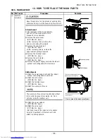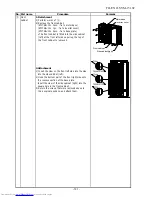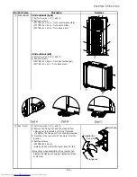
No. Part name
Procedure
Remarks
③
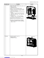
Inverter
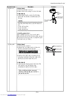
1) Perform works 1 of
①
and
②
.
assembly
Never disassemble the inverter until 1minute
after the power supply was turned off because
there is a fear that an electric shock may occur.
2) Remove screws.
(ST1TØ4×10L 2pcs. : fix to side cabinet (right))
(ST1TØ4×10L 2pcs. : fix to motor base)
(ST1TØ4×10L 1pc. : fix to partition)
3) Remove the cover under inverter box.
(ST1TØ4×10L 1pc.)
4) Disconnect the leads connected to the other parts
from the inverter assembly.
• Lead connected to compressor (3P : white)
• Lead connected to reactor (2P×2 : white)
5) Cut the banding band (3pcs.)
6) Remove the black color lead wire.
(ST2TØ4×8L 1pc.)
7) Remove the duct cover of inverter box.
(ST1TØ4×10L 2pcs.)
8) Remove the inverter box and inverter cover.
9) Remove the power supply cable from the
power supply terminal block.
• Power supply lead L : black
• Power supply lead N : white
- 10
2
-
FILE NO. SVM-15102
Band
Cover under inverter box
Summary of Contents for RAS-2M14S3AV-E
Page 31: ...4 1 Outdoor Unit 4 CONSTRUCTION VIEWS FILE NO SVM 15102 31 Unit mm ...
Page 116: ......


