REMOVAL
PROCEDURE
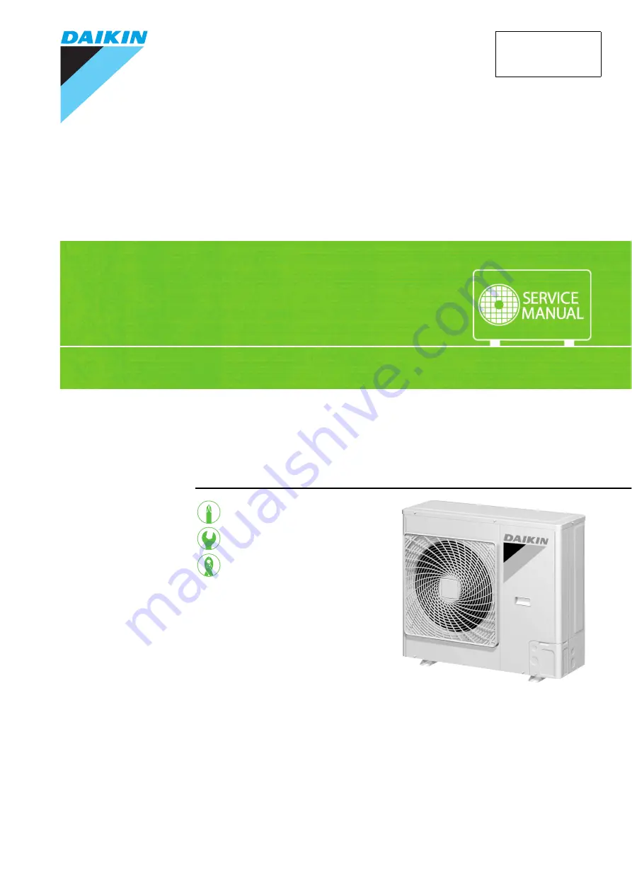
S E R V I C E M A N U A L
Outdoor Unit
Non-Inverter
Pair Type
6.0 kW Class
Si011087
Page 1: ...REMOVAL PROCEDURE S E R V I C E M A N U A L Outdoor Unit Non Inverter Pair Type 6 0 kW Class Si011087 ...
Page 2: ...Service Manual Removal Procedure Outdoor Unit zCooling Only RN60HV1A RN60JV1 ...
Page 3: ... of Outdoor Fan Fan Motor 5 3 Removal of Electrical Component ASSY 7 4 Removal of Sound Blankets 11 5 Removal of Capillary Tube 12 6 Removal of Compressor ASSY Pattern 1 13 7 Removal of Compressor ASSY Pattern 2 15 Note The illustrations may be slightly different depending on the model ...
Page 4: ...efore disassembling work Step Procedure Points 1 Remove the top panel Piping may be slightly different from the illustrations 1 Remove the 8 screws of the top panel 2 Pull the suction grille to unfasten the hook Take care not to cut your finger by the fins of the outdoor heat exchanger 3 Lift up and remove the top panel Top panel R5423 R5423 R5424 Suction grille R5425 R5426 ...
Page 5: ... the suction grille 2 Remove the front panel 2 1 Remove the screw and remove the front panel 2 When reassembling fit the 5 hooks 3 Remove the piping cover front 1 Remove the screw and remove the piping cover front Step Procedure Points Hook R5427 Front panel 2 R12807 R12808 Piping cover front Hook Hook R13234 ...
Page 6: ...Removal of Outer Panels Si011087 4 Removal Procedure 4 Remove the front panel 1 1 Remove the 6 screws and remove the front panel 1 Step Procedure Points Front panel 1 R12810 R5432 R8322 ...
Page 7: ... Points 1 Disconnect the relay connector for the fan motor Preparation Remove the front panel according to the Removal of Outer Panels 2 Unfasten the hook with a flat screwdriver Put the fan motor lead wire through the back of the fan motor when reassembling so as not to be entangled with the outdoor fan 3 Release the fan motor lead wire from the partition plate R15492 Hook R5436 R3249 Lead wire O...
Page 8: ...r and the shaft of fan motor 5 Remove the 4 screws and remove the fan motor Be sure to remove the lower screws first If the upper screws are removed first the fan motor may tilt or fall because the center of its gravity is toward the front It may cause injuries M5 16 Step Procedure Points Lock washer Nut R15404 13 mm R12301 R12834 D cut D cut Lock washer R12835 R5439 ...
Page 9: ...for 10 minutes or more after turning off all power supplies before disassembling work Step Procedure Points 1 Remove the side panel Preparation Remove the top panel front panel 1 2 and piping cover front according to the Removal of Outer Panels 1 Remove the 9 screws and remove the right side panel Right side panel R15402 R15488 Hook R5442 ...
Page 10: ...citor C12R 2 Detach the outdoor temperature sensor Remove the sensor fixing plate 3 Disconnect the terminals of the outdoor temperature thermostat S1T Step Procedure Points R16172 White Red Fan motor capacitor C12R R12813 Outdoor temperature sensor R12814 R15481 Outdoor temperature thermostat S1T to X11A orange to X11A black S1T R15472 L H C to K1M 4 white ...
Page 11: ...R Compressor capacitor C11R 6 Cut the 3 clamps Compressor lead wire Pattern 1 S yellow C blue R red Pattern 2 S yellow C blue R red 7 Disconnect the blue terminal K1M 2 Step Procedure Points R15486 Compressor capacitor R15482 to magnetic contactor K1M 6 red R17612 A2 B2 A1 B1 to compressor R terminal red to compressor S terminal yellow R15483 R12819 S R C C R S R13618 R15484 Blue ...
Page 12: ...t ASSY Si011087 10 Removal Procedure 8 Detach the clamp for the compressor lead wire rear side 9 Lift the electrical components ASSY to unfasten the 2 hooks and remove it Step Procedure Points R6749 R15485 Electrical components ASSY ...
Page 13: ...edure Points 1 Remove the sound blanket top Preparation Remove the electrical components ASSY according to the Removal of Electrical Components ASSY Since the piping ports on the sound blanket are torn easily remove the blanket carefully 2 Remove the sound blanket body Some models have outer and inner sound blankets Sound blanket top R16241 Sound blanket body R16242 R17613 Sound blanket outer Soun...
Page 14: ...the refrigerant gas in the atmosphere Make sure to collect all the refrigerant gas Cautions for restoration 1 Restore the piping by non oxidation brazing 2 Avoid excessive heating Keep below 120 C In case of difficulty with gas brazing machine 1 Disconnect the brazed part where is easy to disconnect and restore 2 Cut pipes on the main unit with a tube cutter in order to make it easy to disconnect ...
Page 15: ...ter turning off all power supplies before disassembling work Step Procedure Points 1 Remove the terminal cover 2 Disconnect the compressor lead wires Be careful so as not to burn the compressor terminals or the name plate S yellow C blue R red 3 Remove the gasket Terminal cover R5455 Terminal cover fixture R5456 Yellow S Blue C Red R R5457 R12819 S R C Gasket R5458 ...
Page 16: ...f difficulty with gas brazing machine 1 Disconnect the brazed part where is easy to disconnect and restore 2 Cut pipes on the main unit with a tube cutter in order to make it easy to disconnect Before working make sure that the refrigerant gas is empty in the circuit Be sure to apply nitrogen replacement when heating up the brazed part 5 Heat up the brazed part of the discharge side and disconnect...
Page 17: ...ure to wait for 10 minutes or more after turning off all power supplies before disassembling work Step Procedure Points 1 Remove the nut and remove the terminal cover 2 Disconnect the compressor lead wires S yellow C blue R red Terminal cover R5414 Nut Rubber washer Terminal cover R15505 Red R Blue C Yellow S R5416 C R S R13618 ...
Page 18: ... refrigerant gas in the atmosphere Make sure to collect all the refrigerant gas Cautions for restoration 1 Restore the piping by non oxidation brazing 2 Avoid excessive heating Keep below 120 C In case of difficulty with gas brazing machine 1 Disconnect the brazed part where is easy to disconnect and restore 2 Cut pipes on the main unit with a tube cutter in order to make it easy to disconnect 4 R...
Page 19: ...e circuit When withdrawing the pipes be careful not to pinch them firmly with pliers The pipes may get deformed Provide a protective sheet or a steel plate so that the brazing flame cannot influence peripheries Be careful so as not to burn the compressor terminals the name plate the heat exchanger fins Step Procedure Points Suction pipe Compressor ASSY R17614 ...
Page 20: ...Revision History Month Year Version Revised contents 01 2013 Si011087 First edition ...
Page 21: ...ries supplied or specified by Daikin Ask a qualified installer or contractor to install those parts and accessories Use of unauthorised parts and accessories or improper installation of parts and accessories can result in water or refrigerant leakage electrical shock fire or explosion z Read the User s Manual carefully before using this product The User s Manual provides important safety instructi...