background image

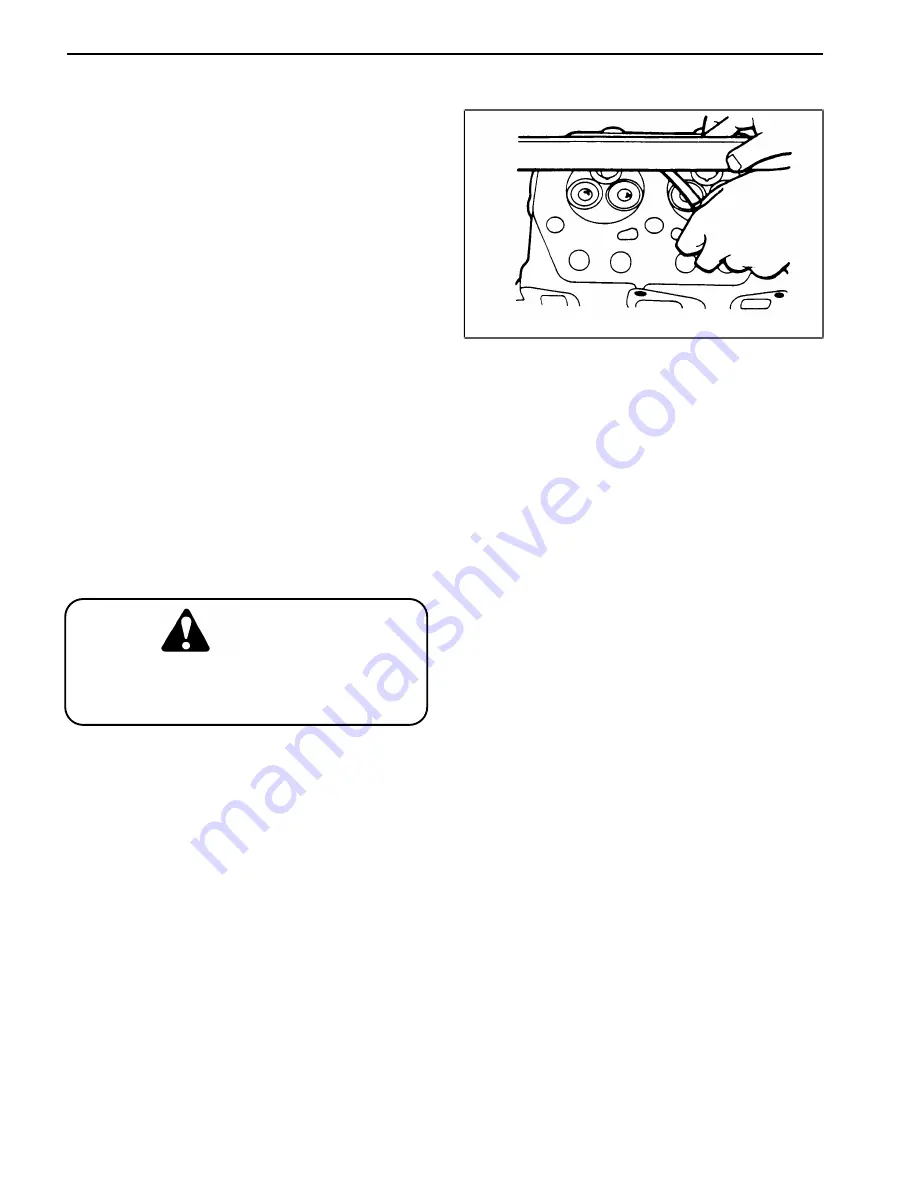
Cylinder Head Servicing (Fig. 54) 

1. Use a spring compressor to compress the valve 
springs. Remove the retainer locks (keepers), retainers, 
and valve springs. Place each part in a holder or rack 
so that they can be replaced in their original position. 

2. Remove the valves and place them in position in the 
rack. Examine each valve for indications of burning, 
pitting, heavy carbon deposits or wear. The condition of 
the valves can give important clues to other components 
which may require service (example: improper valve 
clearance, worn valve guides, damaged seals, etc.). 
Remove the valve seals. 

3. Remove all of the carbon deposits from the combus-
tion chamber using a scraper and wire brush. 

4. Clean the cylinder head thoroughly with solvent or 
degreasing solution and dry. Inspect it carefully for 
cracks. 

5. Remove all carbon deposits from the valve guide 
bores with a valve guide cleaner. Use a valve guide 
bristle brush to remove loosened carbon deposits in the 
valve guide. Push a solvent soaked cloth through the 
valve guides to remove all foreign materials. 

6. Use compressed air to ensure that the oil passage 
way through the head is not clogged. 

Wear eye protection during use of com-
pressed air. Limit air pressure to 40 psi 
(280 kPa). 

7. Check the flatness of the cylinder head lower surface 
using a straight edge and feeler gauge. Be sure to check 
the surface variation crosswise, lengthwise, and diago-
nally. If a surface flatness variation greater than 0.002 
inch (0.05 mm) exists, the cylinder head or cylinder 
block must be replaced or resurfaced. 

8. Use a micrometer and a small hole gauge to check 
the valve guide to valve stem clearance. The valve and 
valve guide should be replaced if the clearance exceeds 
the following limits: 

Intake Valve  . . . . . . . . . . . . . . . .  0.0039 inch (0.10 mm) 
Exhaust Valve . . . . . . . . . . . . . . .  0.0059 inch (0.15 mm) 

Figure 54 

Checking cylinder head distortion 

Cylinder Head Overhaul 

Page 4 - 48 

Groundsmaster

® 

300 Series 

Summary of Contents for Groundsmaster 328-D

Page 1: ...ts Catalogs for your machine Replacement Operator s Manuals are available by sending complete Model and Serial Num ber of traction unit and cutting unit to The Toro Company 8111 Lyndale Avenue South Minneapolis MN 55420 The Toro Company reserves the right to change product specifications or this publication without notice This safety symbol means DANGER WARN ING or CAUTION PERSONAL SAFETY IN STRUC...

Page 2: ......

Page 3: ...ic Schematics 5 6 Hydraulic Flow Diagrams 5 7 Special Tools 5 10 Troubleshooting 5 12 Testing 5 18 Adjustments 5 22 Repairs 5 26 Chapter 6 Electrical System Wiring Schematics 6 2 Special Tools 6 3 Troubleshooting Groundsmaster 345 6 6 Troubleshooting Groundsmaster 322 D 325 D 6 12 Testing 6 18 Repairs 6 30 Chapter 6A Electrical System S N 21000000 Up Wiring Schematics 6 1 Special Tools 6 2 Electri...

Page 4: ...5 Adjustments Repairs 11 8 Chapter 12 Triflex 88 Cutting Unit Specifications 12 2 General Information 12 3 Troubleshooting 12 4 12 5 Adjustments Repairs 12 13 Chapter 13 Guardian 72 Recycler Cutting Unit Specifications 13 2 Troubleshooting 13 3 13 4 Adjustments Repairs 13 7 Groundsmaster 300 Series ...

Page 5: ...ng area 5 Keep all shields and safety devices in place If a shield safety device or decal is defective or damaged repair or replace it before operating the machine Also tighten any loose nuts bolts and screws to make sure machine is in safe operating condition While Doing Maintenance Troubleshooting Testing Adjustments or Repairs 3 j Improper operation maintenance trou bleshooting testing adjustme...

Page 6: ...r roll possibly resulting in personal injury or death 19 Traverse slopes carefully Do not start or stop sud denly when traversing slopes or when traveling uphill or downhill 20 If engine stalls or machine loses headway and cannot make it to the top of a slope do not turn machine around Always back slowly straight down the slope 21 The grass deflector s must always be installed and in lowest positi...

Page 7: ... proper specifications See Cutting Unit Op erator s Manual 34 If machine is equipped with roll over protection ROPS periodically inspect the roll bar and roll bar mounting Repair as necessary Do not weld cut drill or modify roll bar in any manner 35 Make sure all hydraulic line connectors are tight and all hydraulic hoses and lines are in good condition before applying pressure to the system 36 Ke...

Page 8: ...tire service 45 When changing attachments or performing other service use the correct blocks hoists and jacks Always use jack stands to safely support the machine when it is raised by a jack or hoist 46 At the time of manufacture the machine conformed to safety standards in effect for riding mowers To ensure optimum performance and continued safety certification of the machine use genuine TORO rep...

Page 9: ...25 D on the Equipment Operation and Serv ice History Report Form Use this information when referring to your machine TORQUE SPECIFICATIONS 3 Capscrew Markings and Torque Values U S 3 Capscrew Markings and Torque Values Metric 3 EQUIPMENT OPERATION AND SERVICE HISTORY REPORT FORM Insert Operator s Manuals and Parts Manuals for your Groundsmaster 345 322 D or 325 D at the end of this section Grounds...

Page 10: ...78 1 8 0 1250 3 175 5 8 0 6250 15 875 9 64 0 140625 3 572 41 64 0 640625 16 272 5 32 0 15625 3 969 21 32 0 65625 16 669 11 64 0 171875 4 366 43 64 0 671875 17 066 3 16 0 1875 4 762 11 16 0 6875 17 462 13 64 0 203125 5 159 45 64 0 703125 17 859 7 32 0 21875 5 556 23 32 0 71875 18 256 15 64 0 234375 5 953 47 64 0 734375 18 653 1 4 0 2500 6 350 3 4 0 7500 19 050 17 64 0 265625 6 747 49 64 0 765625 19...

Page 11: ...______________________________________ ________________________________________________________________________________________________________________________________________________________ ________________________________________________________________________________________________________________________________________________________ _______________________________________________________...

Page 12: ...Torque Specifications Page 2 4 Rev A Groundsmaster 300 Series ...

Page 13: ...erial Number __________ __________ Deck Model and Serial Number __________ __________ Engine Numbers ____________________ Transmission Numbers ____________________ Drive Axle s Numbers ____________________ Date Purchased ____________________ Warranty Expires__________ Purchased From ____________________ Contacts Parts Phone Service Phone Sales Phone See your TORO Distributor Dealer for other Publi...

Page 14: ...tor Belt Tension B Level Inspect Cooling System Hoses Service Replace Transmission Oil Filter Service Air Filter Check Governor Oil Level Decarbon Spark Arrestor Muffler Check Rear Wheel Toe In and Steering Linkage C Level Torque Wheel Lug Nuts Service Replace Fuel Filter Change Transmission Oil Change Cutting Unit Gear Box Oil Replace Spark Plugs Pack Rear Wheel Bearings D Level Torque Head Adjus...

Page 15: ...e Operation Fuel Level Engine Oil Level Cooling System Fluid Level Dust Cup and Baffle Air Filter Radiator Screen for Debris Unusual Engine Noises Unusual Operating Noises Transmission Oil Level Hydraulic Hoses for Damage Fluid Leaks Tire Pressure Instrument Operation Condition of Blades Lubricate All Grease Fittings 1 Touch up damaged paint Immediately after every washing regardless of the interv...

Page 16: ...hnician Service every 50 hours B Service every 100 hours C Service every 200 hours Check Battery Fluid Level Change Engine Oil and Filter Replace Transmission Oil Filter Check Battery Cable Connections Check Fan and Alternator Belt Tension Service Air Filter Lubricate All Grease Fittings Inspect Cooling System Hoses Check Governor Oil Level Lubricate Brake Cables A Service required Decarbon Spark ...

Page 17: ... and Serial Number __________ __________ Deck Model and Serial Number __________ __________ Engine Numbers ____________________ Transmission Numbers ____________________ Drive Axle s Numbers ____________________ Date Purchased ____________________ Warranty Expires__________ Purchased From ____________________ Contacts Parts Phone Service Phone Sales Phone See your TORO Distributor Dealer for other...

Page 18: ...em Hoses Service Replace Transmission Oil Filter Service Air Filter Decarbon Spark Arrestor Muffler Check Rear Wheel Toe In and Steering Linkage C Level Torque Wheel Lug Nuts Service Replace Diesel Water Separator Filter Replace Electric Fuel Pump Filter Check Fuel Lines and Connections Change Cutting Unit Gear Box Oil Pack rear wheel bearings 2WD Change Rear Axle Lubricant 4WD Change Transmission...

Page 19: ...evel Drain Water Fuel Separator Dust Cup and Baffle Air Filter Radiator Screen for Debris Unusual Engine Noises 1 Unusual Operating Noises Transmission Oil Level Hydraulic Hoses for Damage Fluid Leaks Tire Pressure Instrument Operation Condition of Blades Lubricate All Grease Fittings 2 Touch up damaged paint 1 Check diesel glow plug and injector nozzles if hard starting excess smoke or rough runn...

Page 20: ...id and Cable Connections Replace Engine Oil Filter Change Transmission Oil Lubricate Grease Fittings Check Fan and Alternator Belt Tension Replace Transmission Oil Filter Lubricate Brake Cables Inspect Cooling System Hoses Service Air Filter Check Cutting Unit Gear Box Oil Level A Service required Decarbon Spark Arrestor Muffler Clean Under Cutting Unit Belt Covers Check Rear Wheel Toe In and Stee...

Page 21: ...rk plug Motorcraft AGSF22C or AGRF22 or equivalent Spark plug gap 0 040 in 1 0 mm Crankcase oil capacity 3 5 U S qt 3 25 liter including filter Oil service classification API SG SG CC SG CD Oil viscosity Ambient temperature single viscosity oil 10 to 60 F SAE 10 10 to 90 F SAE 20 Above 32 F SAE 30 Above 50 F SAE 40 Ambient temperature multi viscosity oil Below 60 F SAE 5W 30 10 to 90 F SAE 10W 30 ...

Page 22: ...Light brown insulator tip indicates correct spark plug and heat range B Black or oily insulator tip indicates an excessively rich fuel mixture possibly caused by a dirty air cleaner element or a carburetor that is set too rich C Light gray or blistered white insulator indicates overheating caused by a lean carburetor setting or incorrect spark plug heat range too high IMPORTANT A cracked fouled or...

Page 23: ...ernator in position after proper tension is achieved and tighten alternator and brace bolts to se cure adjustment Figure 1 1 Alternator 2 Brace Coolant Fan Belt Adjustment Fig 2 A new fan belt is to be tensioned to 45 lbs A used belt is to be re tensioned to 28 lbs 1 To adjust belt tension loosen upper and lower nuts securing idler arm to front engine mount 2 Pull out on idler arm until desired be...

Page 24: ...nal adjustment of governor can be performed To against possible personal injury parking brake and keep hands feet face and other parts of body away from fan and other moving parts WARNING Figure 3 2 Start engine and move throttle to SLOW position Allow engine to warm up to normal operating tempera 1 1 32 0 8 mm 4 Stop ture 2 Throttle rod 5 Throttle arm 3 Carbruetor idle speed screw 3 Rotate thrott...

Page 25: ...rnally IMPORTANT Never rotate anti surge screw in too far so that speed of engine increases 9 Bump throttle lever with your hand so engine speeds up momentarily If governor is working properly engine speed should return to normal within one or two surges of governor More than two surges of governor usually indicates that the anti surge screw must be turned in slightly more than it is When adjustme...

Page 26: ...nside ring D Align ring end gaps with key slot in pulley 2 Align pulley key slot with crankshaft key Install pulley approximately 1 4 onto crankshaft 3 Insert fourth locking ring taper to taper with third ring 4 Insert bolt through special washer Shoulder on washer contacts shoulder of fourth locking ring 5 Draw pulley onto crankshaft by tightening crankshaft bolt Resistance will be felt as cranks...

Page 27: ...hose from fuel trap on carbruetor 12 Disconnect choke control cable from carburetor 13 Disconnect throttle control cable from governor 14 Remove fuel line from inlet side of fuel pump NOTE Be prepared to insert a plug into fuel line to prevent fuel spill 15 Remove capscrews securing fan shroud to radiator so fan shroud can be move during engine removal for cooling fan clearance 16 Attach a short s...

Page 28: ...G 411 413 Engine Service Manual for an explana tion of Ford corporate date system Listed below is a summary of changes from the four 4 main bearing design to the five 5 main bearing design of the VSG 411 engine Cylinder block New five main bearing design Crankshaft Same as VSG 413 Crankshaft lower main bearing No change Crankshaft upper main bearing No change Crankshaft rear oil seal retainer Same...

Page 29: ...e Linkage Adjustment 15 Cylinder Head Removal 47 TROUBLESHOOTING 15 Cylinder Head Servicing 48 TESTING 18 Valve Guides 49 Glow Plug Test 18 Valves 49 Compression Test 19 Valve Seats 50 Nozzle Tests 20 Valve Springs 51 Injection Pump Test 22 Rocker Arm and Rocker Shaft Service 51 Injection Timing Test 23 Cylinder Head Reassembly and Installation 52 Fuel Pump Test 24 CYLINDER BLOCK OVERHAUL 53 Therm...

Page 30: ... may dictate that the work be done at a qualified diesel engine repair facility The engine used in the Groundsmaster 322 D 325 D mower is manufactured by Mitsubishi Heavy Industries Limited Service and repair parts for Mitsubishi engines are supplied through TORO Distributors Repair parts may be ordered by TORO Part Number If no parts list is available be sure to provide your dealer or distributor...

Page 31: ... Water oulet fitting 11 Crankshaft 20 Cylinder block 2 Glow plug 9 Oil screen 16 Connecting rod 3 Intake valve 12 Gear case 21 Push rod 3 Intake manifold 10 Oil pan 17 Push rod 4 Exhaust valve 13 Oil pan 22 Tappet 4 Nozzle holder 11 Oil filler cap 18 Tappet 5 Water pump pulley 14 Oil screen 23 Camshaft 5 Cylinder head 12 Rocker cover 19 Camshaft 6 Water pump 15 Oil filler cap 24 Rear oil seal 6 In...

Page 32: ...__________________________________________________ ________________________________________________________________________________________________________________________________________________________ ________________________________________________________________________________________________________________________________________________________ ___________________________________________...

Page 33: ...___________________________________________________________________ ________________________________________________________________________________________________________________________________________________________ ________________________________________________________________________________________________________________________________________________________ Engine Item Standard Speci...

Page 34: ...mm 0 012 in Oversize 0 25 0 50 0 75 mm 0 01 0 02 0 03 in Piston Pin Type Semi floating Outside Diameter 19 mm 0 748 in Pin to Piston Clearance 0 08 mm 0 003 in Pin to Connecting Rod Clearance Press fit load 1000 500 kg 2200 1100 lb Piston Rings Number of Rings 3 Compression No 1 Chrome plated semi keystone type No 2 and No 3 Tapered 1 Oil Chrome plated ring with coil expander Compression Ring Widt...

Page 35: ...____________________________________________________________________________ ________________________________________________________________________________________________________________________________________________________ ________________________________________________________________________________________________________________________________________________________ _________________...

Page 36: ...________ ________________________________________________________________________________________________________________________________________________________ ________________________________________________________________________________________________________________________________________________________ _____________________________________________________________________________________...

Page 37: ...________________________________________________ Electrical System Item Standard Specification Repair Limit Service Limit Starter Type Solenoid shift type Nominal Output 2 0 kW 12V Direction of Rotation Clockwise as viewed from pinion side No load Characteristics Cold Terminal Voltage Current 11V 130A max at 20 C 68 F Speed 3850 rpm min Height of Brush 11 5 mm 0 45 in 1 7 mm 0 07 in Spring Pressur...

Page 38: ...________________________________________________________________________________________________________________________________________________ ________________________________________________________________________________________________________________________________________________________ ______________________________________________________________________________________________________...

Page 39: ...gine Compression Test Kit Fig 5 Diesel engine compression test kit 0 1000 PSI Gauge allows testing of diesel engines to check general oper ating condition of engine Includes case guage with hose glow plug hole adapters and instructions Figure 5 Piston Pin Tool Fig 6 Piston pin tool is used to remove and install the wrist pin without distorting the piston Inludes an adapter for use with Mitsubishi ...

Page 40: ... Nozzle tester adapter is required to test the fuel injection nozzles Figure 8 Camshaft Bushing Tool Fig 9 The camshaft bushing removal and installation tool is used in conjunction with a soft metal hammer to remove or install the camshaft bushing in the Mitsubishi K3D engine Figure 9 Special Tools Page 4 12 Groundsmaster 300 Series ...

Page 41: ...No 1 NOTE There are two TDC positions compression and intake strokes At compression TDC the rocker arms will not move when the crankshaft pulley is rotated a small distance each way Compression TDC is where the valves are to be adjusted 6 Measure the valve clearance by using a thickness gauge inserted between the valve stem and rocker arm The correct valve clearance for both the intake and exhaust...

Page 42: ... from damper spring adjusting bolt Fig 14 and loosen adjusting bolt to remove damper spring tension NOTE If tie rod cover was removed make sure governor tie rod has been pushed to the high speed position before cover is installed 4 Loosen the lock nut on the high speed set bolt Fig 13 and adjust maximum engine speed to setting A by rotating the high speed set bolt Tighten lock nut after adjusting ...

Page 43: ...ottle cable conduit does not interfere with the full range of motion of the throttle lever or governor lever Troubleshooting Giving Immediate attention to any indication of a prob lem can prevent major failures and increase the life of the engine Figure 15 1 Governor lever 4 Throttle cable 2 Cap screw and nut 5 Throttle cable conduit 3 Throttle lever Never make more that one adjustment at a time t...

Page 44: ...Troubleshooting Page 4 16 Groundsmaster 300 Series ...

Page 45: ...Groundsmaster 300 Series Page 4 17 Troubleshooting ...

Page 46: ... signs of a burnt glow plug Figure 16 end tube NOTE If the metal of the glow plug end is melted it is a sign of cylinder overheating See Engine Overheats in the Troubleshooting section of this chapter 4 Connect the positive battery terminal to the glow plug terminal and the negative battery terminal to the plug body If the glow plug glows red hot the glow plug is operating correctly 5 Replace any ...

Page 47: ...al Tools section of this chapter 3 Connect the high pressure compression gauge to the adapter 4 Hold fuel shut off lever in closed position to prevent fuel delivery during compression test This will prevent wash down of cylinders and inaccurate readings 5 Crank the engine with the starter motor until you get a stable gauge reading 6 If the pressure is less than 26 kg cm2 370 psi it will be necessa...

Page 48: ...le to the adapter 2 Pump the handle several times to purge air from the nozzle mechanism 3 Allow pressure to dissipate before performing the test 4 Operate the pump handle slowly and observe the gauge to determine the pressure at which the nozzle opens and the fuel is sprayed 5 Verify that starting pressure is within the following limits 2 Minimum starting pressure 120 kg cm 1700 psi 2 Maximum sta...

Page 49: ...e and must be replaced Spray Test For proper combustion the nozzle must effectively at omize the injected fuel 1 Operate the pump handle at a rate of 20 30 strokes per minute 2 Observe the injector nozzle spray The spray pattern should be finely atomized in a broad straight stream Fig 19 3 If the nozzle fails to spray properly it must be cleaned repaired or replaced See Nozzle Service in the Fuel ...

Page 50: ...ve the nozzle from the cylinder head C Connect the fuel delivery pipe to the nozzle as sembly so the tip of the nozzle is pointed away from the engine Tighten the fitting securely D Put the throttle control in the FAST position Turn the ignition key to the START position to crank the engine Observe the nozzle j The injection pump forces fuel from the noz zle under extremely high pressure Always po...

Page 51: ...umber 1 cylinder should be loose and the valves closed If either push rod is tight rotate the engine crankshaft one full revolution and inspect the push rods again 5 Turn the ignition switch ON so the electric fuel pump will supply fuel through the injection pump and out the number 1 delivery valve holder 6 Rotate the engine crankshaft SLOWLY in the normal direction until the flow from the number ...

Page 52: ...el pumped in during a 15 second time interval The standard pump rate is approxi mately 8 ounces 225 cc in 15 seconds 4 If the fuel delivery rate is below the standard value the pump should be disassembled and checked See Fuel Pump Service in the Fuel System Repairs section of this chapter Thermostat Test Fig 23 Figure 22 If the engine overheats and a faulty thermostat is sus pected the thermostat ...

Page 53: ...Cylinder and Cylinder Block Overhaul Before removing any parts disassembly or overhaul of the Mitsubishi engine it is very important to understand the nature and probable cause of the problem that made an overhaul necessary When the engine trouble is caused by worn cylinders rings or valves one or more of the following symptoms will occur 1 Low engine power and a decrease in compression pressure 2...

Page 54: ... recombustion without being discharged into the atmosphere The fumes within the cylinder block flow into the rocker cover through holes in the valve tappets and the push rod clearance holes They are carried through a rubber air breather pipe from the rocker cover to the inlet pipe and then to the combustion chamber The air breather pipe rubber hose should be replaced if it is damaged or shows any ...

Page 55: ...ys with 5 lbf 22 N of force applied If deflection is incorrect proceed to step 4 If correct proceed to step 5 4 Loosen locknut securing idler pulley Push idler pulley against belt until proper deflection is achieved and tighten idler pulley locknut 5 Install fan belt guard and secure with capscrews Close and latch hood To replace belt 1 Do steps 1 and 2 above 2 Loosen locknut securing idler pulley...

Page 56: ...rews which secure fan mount to front of cylinder head cylinder block and muffler bracket 8 Remove fan assembly from machine 9 Remove cotter pins slotted nuts woodruff keys and washers from ends of the fan shaft Note number and placement of washers 10 Remove pulley from end of shaft it may be neces sary to use a puller 11 Remove cap screws and lock washers which retain fan to fan hub Remove fan hub...

Page 57: ... key in fan shaft and slide fan hub onto shaft Install fan to fan hub with cap screws and lock washers Fit flat washer and shim washer s to shaft and install slotted hex nut Torque nut from 50 to 70 ft lb 68 to 94 N m IMPORTANT If hex nut slot and cotter pin shaft hole do not align after applying correct torque to slotted hex nut remove nut and add shim washers until alignment is correct DO NOT lo...

Page 58: ...This page is intentionally blank External Engine Components Repair Page 4 28 2 Rev D Groundsmaster 300 Series ...

Page 59: ...lamp and buzzer on the control panel if the oil pressure drops below safe levels during opera tion The switch is located on the oil pump at the rear of the right hand side of the cylinder block The switch and lamp circuit can be tested with a 12 VDC battery With the switch removed the warning lamp should light and buzzer sound when it is connected in series with the switch and battery Removing the...

Page 60: ...Outer Rotor to body clearance should be checked with a feeler gauge If clearance exceeds the service limit replace the rotor assembly 2 Outer rotor to Inner Rotor clearance should be checked with a feeler gauge If clearance exceeds the service limit replace the rotor assembly Check the coupling end of the Inner Rotor shaft for cracks or damage 3 Rotor to cover clearance should be check with a feel...

Page 61: ... The Inner and Outer Rotors have a dimple which faces outward from the Pump Body 4 Place the Pump Body along with a new oil Pump Body Gasket in position and rotate the rotor assembly until the inner rotor shaft couples with the slot in the injector pump cam shaft 5 Position the Pump Cover on the dowel pins and secure the pump into positions with the four bolts washers and lock washers Torque the b...

Page 62: ...id 5 Start to thread the solenoid into the cylinder block 6 Push the plunger on the solenoid fully in and hold it in this position 7 Rotate the emergency engine stop lever to the STOP position counterclockwise 8 Continue to hold the solenoid plunger in and thread the solenoid into the cylinder block until the inner end of the plunger contacts the control rack of injector pump Contact will be indic...

Page 63: ...ter bypass hose 5 Remove the six bolts fastening the water pump to the cylinder block Water Pump Inspection 1 Inspect all hoses for cracks or leaks 2 Rotate the water pump impeller and shaft If the bearings do not rotate smoothly or are noisy the water pump must be replaced the water pump has no replace able components Water Pump Reassembly Reassemble in reverse order of disassembly Use a new wate...

Page 64: ...gin to operate and force fuel out around the screw loosened in step 2 Fuel will fill the filter bowl and then flow out around the screw When a solid stream of fuel flows out around the screw tighten the screw and turn the key switch OFF 4 Open the air bleed screw on the fuel injection pump 5 Turn the ignition key switch to the ON position The electric fuel pump will begin to operate and force fuel...

Page 65: ...ut of the loose pipe connection 4 Tighten the pipe connector Figure 37 5 Repeat steps 1 4 for the No 2 and No 3 injector nozzle and holder Fuel Pump Service Fig 38 The only serviceable parts of the fuel pump are the magnet filter and the gaskets on each end of the filter 1 Disconnect the fuel pump wires from the wiring har ness and ground connection 2 Disconnect the fuel hoses from the pump Plug t...

Page 66: ...plunger valve side out plunger spring valve o ring washer and spring retainer Make sure the plunger operates freely 7 Install the filter and cover gaskets magnet filter and cover Tighten the cover to prevent air leaks 8 Install the fuel pump to the frame Connect the fuel lines and electrical wires 9 Bleed the fuel system See Bleeding the Fuel System in this section of the book Figure 39 1 Spring r...

Page 67: ... surging hunting Be fore removal and disassembly of the engine the follow ing inspections are recommended 1 Remove the tie rod cover and operate the speed control lever The injection pump control rack should move as the lever is operated 2 If the control rack does not move remove the tie rod retaining spring and tie rod from the control rack The control rack should now move freely when operated by...

Page 68: ...otated by the control pinion which meshes with the plunger lower collar to directly turn the plunger As the engine turns the injection pump camshaft rotates to move the control rack by way of the governor weights governor sleeve and lever The control rack slides to turn the control pinions Movement of the control rack to the right decreases the fuel injection rate and movement to the left increase...

Page 69: ... in order for the control rack to travel completely to the left over injection Once started the action of the governor causes the control rack to move to the right less fuel until the corner of the smoke set plate engages the shoulder of the Ungleich set plate The amount of control rack movement is now restricted by the locations of the smoke set plate and the Ungleich set plate During extreme loa...

Page 70: ...to nearly zero while preventing fuel from flowing from the tube Figure 45 Inter Cylinder Injection Control Fig 46 The amount of fuel delivered to each of the three cylin ders is adjusted by means of adjusting plates These plates function as a cam to position the plunger barrel within the pump housing IMPORTANT Do not remove the Adjusting Plates from the pump housing If removed re calibration by a ...

Page 71: ...adjusting shims under the pump The shims determine the injec tion timing 6 Straighten the locking tabs on the plate which retains the Tappet Guide Pin Rotate the pin 180 push in on the Tappet slightly and remove the Guide Pin and Tap pet 7 Remove the Lower Seat Plunger Spring Upper Seat Control Pinion and Plunger 8 Remove the Delivery Valve Holder Gasket 0 ring Valve Spring and Delivery Valve Push...

Page 72: ...nstall the Control Rack Smoke Set and Ungleich plates retainer springs and fasteners 2 If the adjusting plate assemblies have been removed reinstall them paying careful attention to install them according to the marks scribed on the pump housing and plates 3 Install the Plunger Barrel into the bore in the top of the Pump Housing Make sure that the groove in the barrel aligns with the pin in the si...

Page 73: ...rocedure for the other remaining cylin ders 11 Install the injection pump to the cylinder block Make certain that the same number and size shims that were under the pump when removed are replaced correctly 12 Connect the Tie Rod and Tie Rod Retaining Spring to the Control Rack 13 Push the control rack to the high speed position left and reinstall the tie rod cover using a new cover gasket 14 Reass...

Page 74: ...d the help of a competent diesel engine service shop should be sought Injection Pump Timing and Adjustment Adjusting the shim thicknesses as explained on Injec tion Timing Test will adjust the injection timing NOTE If timing requires adjustment and the engine has not been worked on or the shim thickness changed the injection pump components and camshaft should be inspected for wear or damage Fuel ...

Page 75: ...essure spring flange pressure pin and distance piece 6 Remove the nozzle from the retaining nut If it is difficult to remove tap it lightly with a rubber or wooden mallet Be careful not to hit or damage the protruding tip of the nozzle needle valve Inspection and Cleaning 1 Clean the inside and outside of the retaining nut in clean diesel fuel to remove carbon or fuel deposits Inspect the lower se...

Page 76: ...spill 12 Remove main fuel return hose at injector nozzle connection 13 Remove capscrews attaching fan belt guard and remove fan belt guard 14 Remove capscrews securing fan shroud to radiator so fan shroud can be move during engine removal for cooling fan clearance 15 Attach a short section of chain between the two lifting shakles on the engine Attach block and tackle or hoist chain to this short s...

Page 77: ...he injection pipes injection pump to noz zles 4 Remove the rocker cover and breather tube 5 Loosen the two bolts and the cap screw which retain the rocker shaft assembly and remove the rocker shaft 6 Remove the push rods Place each push rod into a marked holder so that it can be replaced in the original position 7 Loosen and remove the cylinder head bolts in the sequence shown Lift the cylinder he...

Page 78: ...ores with a valve guide cleaner Use a valve guide bristle brush to remove loosened carbon deposits in the valve guide Push a solvent soaked cloth through the valve guides to remove all foreign materials 6 Use compressed air to ensure that the oil passage way through the head is not clogged Wear eye protection during use of com pressed air Limit air pressure to 40 psi 280 kPa 7 Check the flatness o...

Page 79: ...earance If the clearance is smaller than the standard size it will be necessary to ream the valve guide bore to obtain the proper clearance Valves Fig 56 1 Carefully clean each valve with a wire wheel to remove all carbon deposits 2 Check the valve face and the valve stem for excessive wear damage cracks or deformation If any of these conditions exist the valve must be replaced It is possi ble to ...

Page 80: ... valve face is making proper contact to the valve seat lightly coat the valve seat area with Prussion blue install the valve rotate the valve 1 4 turn while holding it down and then bring it back to the original position Remove the valve and examine the valve seat The valve seat should show an even wear pattern from contact with the valve Ex amine the valve The dye should be evenly distributed aro...

Page 81: ... the cost of repairing engine damage due to weak valve springs Figure 59 Checking valve spring length Rocker Arm and Rocker Shaft Service Fig 60 1 Disassemble the rocker shaft by removing the outside retaining rings on each end and by removing the two rocker arms stay bolts and seats from the rocker shaft 2 Inspect each rocker arm for signs of wear where they contact the valve tip and push rod con...

Page 82: ...em to the cylinder head 5 Install the glow plugs and glow plug lead wires The glow plugs should be torqued to 10 8 14 5 ft lbs 1 5 2 0 KgM 6 Install the nozzle holder and tighten the bolts evenly to 10 8 14 5 ft lbs 1 5 2 0 KgM 7 Ensure that the cylinder head and cylinder block surfaces are clean Position a new head gasket on the head and insert some dowel pins into two cylinder head bolt holes in...

Page 83: ...rs from their positions in the cylinder block 6 Remove the speedometer drive assembly from the left hand side of the engine by removing the cap screw and clamp and pulling the gear out 7 Turn the engine upside down on the stand and remove the oil drain pan and filter screen spring like screen 8 Remove the crankshaft pulley nut washer lock washer and key 9 Remove the gear case from the front of the...

Page 84: ...ylinder onto the top of the piston When the piston and rod assembly is removed use care to prevent damage to the piston or bearing surfaces 15 Remove the main bearing caps Arrange the re moved caps and bearings according to cylinder order so they may be replaced in the same position upon reassembly NOTE Before removing the main bearing caps meas ure the crankshaft end play 16 Remove the crankshaft...

Page 85: ... in the bushing 5 If the cam surface is damaged or the cam lobe is badly worn it must be replaced Cam lobe height should be measured using a micrometer The standard cam lobe height for both intake and exhaust valves is 1 4079 inches 35 75 mm The maximum allowable wear on cam surface is 0 0394 inch 1 0 mm Replace the camshaft if wear exceeds this amount Figure 65 Removing camshaft bushing Figure 66...

Page 86: ...nce between the crankshaft and its bearings install the crankshaft into the cylinder block place a piece of Plastigauge onto the crank pin or journal and torque the bearing cap with bearing in place DO NOT TURN THE CRANKSHAFT WHEN PLASTIGAUGE IS IN PLACE SINCE THE PLASTIGAUGE WOULD BE DESTROYED Remove the bearing cap and measure the width of the Plasti gauge to determine the clearance If the oil c...

Page 87: ...l clearance can be measured using a micrometer or Plastigauge Refer to Crankshaft Bearings for tolerances Figure 71 Measuring connecting rod thrust clearance Cylinders Fig 72 1 Measure the cylinder bore size in six locations as shown The standard bore diameter is 2 8740 inches 73 mm The cylinder must be rebored and oversized piston and rings installed if the diameter exceeds the standard by 0079 i...

Page 88: ...be used to clean the ring grooves 4 Measure the piston ring side clearances using a thickness gauge If the piston ring side clearance exceeds the service limit in the chart below the ring must be replaced NOTE In the case of a tapered ring No 1 measure the clearance on the bottom or widest area of the ring Figure 73 Measuring piston outside diameter Figure 74 Measuring piston ring side clearance 5...

Page 89: ...eeds 0 0031 inch 0 08 mm the piston and or pin Piston pin removal tool must be replaced Engine Reassembly The engine should be reassembled in the order given in this section The following general precautions should be observed when reassembling the engine 1 Clean each part carefully Pay particular attention to oil holes bearing surfaces and rotating parts 2 Before assembly apply engine oil to all ...

Page 90: ...sed arrow mark and letter or numeral to indicate its position in the cylinder block When installing the no 1 and no 4 bearing caps apply sealant to the upper surface that meets with the cylinder block 5 With the bolts torqued use a dial indicator on the end of the crankshaft to measure the crankshaft end play If the end play exceeds 0197 inch 0 5 mm replace the No 3 main bearing Figure 77 Installi...

Page 91: ...the oil seal into the crankshaft rear oil seal case Apply a light coat of oil to the oil seal lip and install the seal case to the cylinder block NOTE Use a new gasket 8 Install the rear engine plate if it has been removed 9 Install the flywheel onto the crankshaft using the bolts and special washers Torque the flywheel bolts to 83 90 ft lbs 11 5 12 5 KgM Figure 82 Installing oil seal case Grounds...

Page 92: ...the piston and connecting rod make certain that the connecting rod small end is properly positioned at the center of the piston pin 11 Install the piston rings IMPORTANT The piston rings differ in shape from one another Be careful to install them in proper position and with the ring gaps in the directions as illustrated In the case of the oil ring with the coil expander the gap clearance of the ri...

Page 93: ... the shaft if it has been disassem bled 16 With the idler gear mating mark 1 properly aligned with the crankshaft mating mark 1 install the idler gear on to the idler shaft 17 Insert the camshaft and gear assembly into the cylinder block and align the idler gear mark 2 with the camshaft gear mating mark 2 18 Install the injection pump camshaft assembly into the cylinder block and align the idler g...

Page 94: ...g is prop erly installed Apply oil to the outside surface of valve lifters and insert the lifters into the cylinder block in the order of which they were removed Install the push rods into the lifters in the order in which they were removed 32 Install the cylinder head assembly Figure 88 Inserting tappet 33 Install the fuel injection pump 34 Install the oil pump and oil filter if they have been re...

Page 95: ...part number If no parts list is available be sure to provide your Distribu tor with the TORO model number and serial number General maintenance procedures are described in your Operator s Manual Information regarding engine trou bleshooting testing disassembly and assembly is iden tified in the Kubota 05 Series Service Manual Toro part 01090SL Note Refer to Chapter 4 Mitsubishi K3D Diesel En gine ...

Page 96: ...M D975 Fuel Capacity 6 5 U S gallon 24 6 liter Fuel Injection Pump Bosch MD Type Mini Pump Injection Nozzles Mini Nozzle DNOPD Governor Centrifugal Mechanical Idle Speed no load 1500 1650 RPM High Idle no load 3100 3250 RPM Coolant Capacity 6 U S quart 5 7 liter Engine Oil See Operator s Manual Oil Capacity 4 U S quart 3 8 liter with filter Starter 12 VDC 1 4 KW Alternator Regulator 12 VDC 40 AMP ...

Page 97: ...n Wheel Adjustment 23 Traction Control Neutral Adjustment 24 Lift Lever Latch Adjustment 25 REPAIRS 26 Transmission Trunnion Seal Replacement 26 Transmission By Pass Valve 27 Transmission Acceleration Valves 28 Transmission Implement Relief Valve 29 Transmission Charge Relief Valve 30 Transmission Charge Pump 31 Transmission Removal and Installation 33 Transmission Overhaul 34 Separating Transmiss...

Page 98: ...open center Hydraulic Oil The hydraulic system is designed to operate on any high quality detergent oil having the American Petroleum Institute API service classification SF CC or CD Oil viscosity weight must be selected according to anticipated ambient temperature See Hydraulic oil specifications in above chart IMPORTANT DO NOT mix engine oil and automatic transmission fluid or hydraulic system c...

Page 99: ... under pressure can have sufficient force to penetrate the skin and do serious damage If fluid is in ected into the skin it must be surgically removed within few hours by a doctor familiar with this type of injury or gangrene may result WARNING Hydraulic Fitting Installation O Ring Face Seal 1 Make sure both threads and sealing surfaces are free of burrs nicks scratches or any foreign material Fig...

Page 100: ...al Fig 5 2 Always replace the O ring seal when this type of fitting shows signs of leakage 3 Lubricate the O ring with a light coating of oil 4 Turn back the jam nut as far as possible Make sure the back up washer is not loose and is pushed up as far as possible Step 1 5 Install the fitting into the port and tighten finger tight until the washer contacts the face of the port Step 2 6 To put the fi...

Page 101: ...pport seat to get access to by pass valve 2 Rotate by pass valve on transmission counterclock wise 1 2 to 1 turn Opening the valve opens an internal passage in the pump to by pass transmission oil Be cause fluid is by passed the machine can be pushed slowly without damaging the transmission 3 Close by pass valve by rotating it clockwise until it is securely seated Do not exceed 5 to 8 ft lb of tor...

Page 102: ...Hydraulic Schematics 4 Wheel Drive Traction Unit 2 Wheel Drive Traction Unit Hydraulic Schematics Page 5 6 Groundsmaster 300 Series ...

Page 103: ...ation The hydrostatic transmission consists of a charge pump variable dis placement pump and a fixed displacement motor The diagram shows flow of the hydraulic oil during forward operation Groundsmaster 300 Series Page 5 7 Hydraulic Flow Diagrams ...

Page 104: ...end of the lift cylinder Oil displaced from the rod end of the cylinders goes through the oil cooler and back to reservoir NOTE The steering valve will not allow oil to flow through it to the lift valve when the steering wheel is being turned Whenever the steering wheel is not moving the steering valve allows l il ing ci oil to f ow through it O in the rest of the steer rcuit is then trapped Press...

Page 105: ...linder Oil displaced by the other end of the steering cylinder returns to the steering valve through port LT which directs it through the OUT port back to reservoir When the steering wheel stops turning the control valve within the steering valve shifts back to neutral allowing oil to flow through the steering valve out the AUX port to the lift control il ing ci i i valve O in the rest of the stee...

Page 106: ...MMERCIAL be available from a local supplier PRODUCTS Some tools may be listed in the Parts Hydraulic Pressure Gauges Fig 7 Used to take various hydraulic pressure readings for diagnostic tests Low pressure gauge 0 1000 psi high pressure gauge 0 5000 psi and associated hoses and fittings Figure 7 Special Tools Page 5 10 Groundsmaster 300 Series ...

Page 107: ...URE GAUGE Low range gauge to provide accurate reading at low pressure 0 1000 psi This gauge has a protector valve which cuts out when pressure is about to exceed the normal range for the gauge The cutout pressure is adjustable gure 8 4 HIGH PRESSURE GAUGE High range gauge to accommodate pressure beyond the capacity of the low pressure gauge 0 5000 5 FLOW METER This meter measures actual oil flow i...

Page 108: ...e charts that follow contain detailed information to assist in troubleshooting There may possibly be more than one cause for a machine malfunction All causes should be checked in the order in which they are listed on the charts Refer to the Testing section of this Chapter for precau tions and specific test procedures System Operates in Only One Direction Inspect Ok Inspect traction control acceler...

Page 109: ...epair fan or belt Add coolant Close or repair Adjust lever Replace kinked or bent hose or tubing Reduce load on transmission non hydraulic problem Ok Check traction pressure Ok Check charge pump flow Ok Inspect transmission inlet filter Low Low Loose or clogged Repair acceleration valves Repair or replace Inspect Inspect Test Tighten Ok Ok Ok transmission charge implement steering or pump motor pu...

Page 110: ...w Ok Adjust Fill to Close Tighten Adjust use Repair proper or or or tachometer level repair replace repair Inspect Inspect Inspect Ok Ok OK charge implement charge pump relief valve relief valve Defective Defective Defective Repair or replace Repair or shim Repair or shim charge pump implement charge relief valve relief valve Repair or replace transmission Ok Inspect acceleration Low Check tractio...

Page 111: ...cess debris Low or out of adjustment Binding Repair or replace transmission Ok Inspect charge Ok Inspect implement Ok Test steering Tighten or pump motor pump relief valve valve replace Control valve Defective Defective sticking Repair Repair or shim Repair or replace charge implement steering pump relief valve valve Ok Test lift Ok Inspect cylinders lift valve for internal leakage Defective Defec...

Page 112: ...Tighten or pump motor pump relief valve valve replace Control valve Defective Defective sticking Repair Repair or shim Repair or replace charge implement steering pump relief valve valve Ok Check for restric tion in return line OUT port Ok Inspect steering valve NOTE Sticking steering valve plate can cause high steering effort in one direction This is usually caused by excessive heat in the system...

Page 113: ...aulic Ok Inspect steering or worn steering system cylinder for internal linkage leakage Defective Defective Defective Repair linkage and Bleed air from Replace steering adjust toe in hydraulic system cylinder Groundsmaster 300 Series Page 5 17 Troubleshooting ...

Page 114: ...ressure can have sufficient force to penetrate skin and do serious damage If fluid is in ected into the skin it must be surgically removed within few hours by a doctor familiar with this type of injury or gangrene may result WARNING 1 Thoroughly clean the machine before disconnecting or disassembling any hydraulic components Always keep in mind the need for cleanliness when working on hydraulic eq...

Page 115: ...use a tachometer to verify that the engine is running at 3200 50 rpm 8 Observe the pressure measurement on the low pres sure gauge The reading should be 70 150 psi NOTE A higher reading may be obtained due to the back pressure in the system This is acceptable 9 If the pressure is below 70 psi adjust the charge relief valve by adding the required amount of shims from the shim pack NOTE If adding sh...

Page 116: ...lic circuit This is can be caused by parts that are binding or build up of debris under the cutting unit This adds to the amount of force that the hydraulic cylinder must overcome Repair such items before continuing with the hydraulic tests If adding shims to the relief valve does not increase the pressure inspect the condition of the charge pump gerotor and internal housing If the charge pump is ...

Page 117: ...raulic oil reaches normal operating temperature 5 Increase the engine speed to the FULLthrottle setting Figure 10 and use a tachometer to achieve 3200 50 rpm 1 High pressure gauge 0 5000 psi j To prevent damage to gauge and possible personal in ury due to leaking hot oil do not exceed 5000 psi during traction pressure test CAUTION 6 Sit on the seat and with the brakes locked slowly depress the top...

Page 118: ...ne is running at 3200 50 rpm 7 While watching the flow and pressure gauges slowly close the flow control valve load valve until the flow gauge reads 1 0 GPM 8 If the pressure is below 700 psi or 1 0 GPM could not be achieved adjust the implement relief valve by adding the required amount of shims from the shim pack The implement relief pressure must not ex ceed 800 psi CAUTION If adding shims to t...

Page 119: ...ectly secure tapered 1 1 16 in 1 6 mm 4 Nuts 2 Jam nut socket and traction pedal together with slotted nut and 3 Cotter pin slotted nut 5 Friction wheel cotter pin Also tighten jam nut against front of control rod Traction Control Rod Adjustment Serial Numbers Above 50000 Fig 12A 1 Check traction drive neutral position to assure front wheels do not creep refer to Traction Drive Neutral Ad justment...

Page 120: ...e 3 capscrews that secure pump plate to transmission C If wheel is rotating forward lightly tap bottom of pump plate counterclockwise By contrast tap pump plate clockwise if wheel is rotating backward When wheel stops rotating tighten capscrews to secure pump plate D Check that wheel s that are off the ground are NOT rotating with throttle in both SLOW and FAST position If necessary repeat pump pl...

Page 121: ...g screws and lift cover off lift lever to expose the latch 3 Loosen two capscrews on top of the lift lever latch Place lever on rounded tip of latch and slide latch w lever forward until stopping resistance is felt Then tighten capscrews to lock the latch in place Check for free operation of the lift lever by moving lever from RAISE or TRANSPORT to FLOAT position Lift lever should just clear round...

Page 122: ... protector use plastic wrap or a similar material to wrap the shaft This protects the lip of the seal from possible damage when sliding it onto the shaft and pressing it onto the housing 5 Slide the flat washer onto the shaft and install the snap ring into the groove at the end of the shaft Do not use a flat washer that is bent 6 Install the control lever and the interlock switch as sembly on the ...

Page 123: ...because of damage slide the new back up ring into the groove at the center of the valve then install the O ring into the same groove 6 To install the by pass valve screw it into the center section Tighten the valve to 5 8 ft lb 7 Since some oil drained out of the transmission when the by pass valve was removed check the oil level in the axle housing Start the engine and let it run for about one or...

Page 124: ...s bore 7 Check the spring for damage and correct specifica tions Replace the spring if its condition is doubtful Spring specifications are listed in the table below Acceleration Valve Spring Specifications Free Length 2 25 in Number of Coils 23 1 2 Outside Diameter 0 297 0 303 in Pounds per Inch 17 8 To install acceleration valves place a new O ring onto both acceleration valve plugs 9 Slide one a...

Page 125: ...amage If cone is damaged replace it 6 Check the spring for damage and correct specifica tions Replace the spring if its condition is doubtful Spring specifications are listed in the table below Implement Relief Spring Specifications Free Length 0 804 in Number of Coils 10 Outside Diameter 0 260 0 262 in Pounds per Inch 339 7 To install the implement relief valve slide the new O ring onto the imple...

Page 126: ...he spring for damage and correct specifica tions Replace the spring if is condition is doubtful Spring specifications are listed in the table below Charge Relief Spring Specifications Free Length 1 051 in Number of Coils 14 Outside Diameter 0 249 0 251 in Pounds per Inch 13 8 6 To install the charge relief valve slide a new O ring onto the charge relief plug 7 In sequence insert the check ball or ...

Page 127: ...Charge pump housings that have the letters LH and RH on the external surface must be installed with the letters LH positioned closest to the top of the transmission 6 Remove the cap screws holding the charge pump housing against the adjacent pump housing Using a seal protector slide the charge pump housing and gerotor wheel off of the pump shaft The O ring will probably stay in the groove on the i...

Page 128: ...tion i e clockwise The GROUNDSMASTER mower application requires that the LH markings be toward the top of the transmission Having LH toward the bottom of the transmission will result in a complete loss of hydraulic functions NOTE In place of a seal protector use plastic wrap or a similar material to wrap the pump shaft This protects the seal from possible damage when sliding it onto the pump shaft...

Page 129: ...s and fittings 6 Remove the hydraulic lines that connect to the trans mission Cap or plug all hoses and fittings to prevent contamination NOTE To ease reassembly tag all lines as to their proper location 7 Loosen and remove the engine to transmission coupler refer to Removing Drive Coupling of Chapter 10 8 Disconnect and remove the traction pedal rod where it fastens to the transmission 9 Support ...

Page 130: ...and valves is covered on previous pages 1 Before separating the transmission scribe or paint an alignment mark on each housing to assure correct reassembly of the sections 2 Remove the four cap screws in small increments so the three main sections separate evenly As the cap screws are loosened oil will drain from the housings NOTE When the cap screws are first loosened an internal spring load caus...

Page 131: ...pring pins on the control shaft side of the pump housing and one pin on the trunnion shaft side The control shaft must have two pins be cause of the continuous applied force from the traction pedal during operation 6 Mark the control shaft and housing so the shaft can be installed correctly when the parts are reassembled Slide a long punch through the hole at the end of the control shaft and pull ...

Page 132: ...slide the control and trunnion shafts into the housing and swash plate Make sure the control shaft is on the implement relief side of the housing see alignment marks on the shaft and housing Secure the shafts and swash plate together with the spring pins IMPORTANT Use only new spring pins when as sembling the swash plate and shafts two pins through the control shaft and one pin through the trunnio...

Page 133: ... damage Spring specifications are listed in the table below Check Valve Spring Specifications Free Length 0 550 in Number of Coils 10 Outside Diameter 0 217 0 219 in Pounds Per Inch 3 67 C Needle Bearings Check for free rotation and any noticeable damage D Dowel Pins Check the dowel pin on the motor side and the pump side of the center section for wear and damage NOTE Replace any defective parts T...

Page 134: ...oring or damaged splines NOTE Replace any defective part Remember that the cylinder block assemblies must be replaced as a com plete component not individual parts Do not inter change parts between the motor cylinder block assembly and the pump cylinder block assembly be cause the transmission will not operate at its optimum capacity 6 Lubricate the bearing with transmission oil Press the bearing ...

Page 135: ...he kidney shaped grooves The pump valve plate has two V notches in the grooves 3 Apply transmission oil on the surfaces of the pump valve plate and install the recessed groove side of the pump valve plate against the pump side of center sec tion The slot in the valve plate must fit over the locating pin Assure that the center of the valve plate pilots on the needle bearing extending out of the cen...

Page 136: ... it onto the transmission 3 Remove the dipstick from the pipe nipple in the differential assembly and add oil to the proper level 4 Start the engine and operate the traction and lift system controls for approximately five minutes Then turn the engine off 5 Allow the machine to stand idle for approximately two minutes remove the dipstick and check the oil level If the oil level is too high drain th...

Page 137: ...linder is to the outside Hook the chain tension spring through the eye of the cotter pin 5 Connect the hydraulic hoses from the control valve to the cylinder 6 Install the wheel and tighten the nuts to 45 55 ft lb Remove the jack stank and lower the deck to the shop floor 7 Check the level of the hydraulic oil to be sure it is up to the proper level Start the engine and operate the lift cylinder t...

Page 138: ...n for excessive scoring pitting or wear Replace any defective parts 10 Use a new seal kit Items 3 6 10 to replace all O rings seals and back up rings IMPORTANT The dust seal lips must point outward the seal must have the O ring portion facing towards the inside of the cylinder 11 The rod end is retained with 75 90 ft lbs torque and with Loctite Retaining Compound very strong 12 Tighten the piston ...

Page 139: ... 3 Loosen and remove the hydraulic lines that are attached to the valve Cap or plug all of the fittings and hoses to prevent contamination 4 Remove the five cap screws and locknuts that secure the valve and lever to the main frame 5 Lift out the control valve Figure 35 6 Reverse order to install a new or reconditioned con trol valve Groundsmaster 300 Series Page 5 43 Repairs ...

Page 140: ...he spool to remove the spool from the valve body 5 Use a hooked scribe or thin screwdriver to remove the O rings from the inside bore of the valve body be careful not to scratch valve bore finish These O rings are the seals for the spool itself Inspect all components for wear paying special attention to the spool itself Signs of wear on one side of the spool may indicate a bent spool Inspect the s...

Page 141: ...8 Seat Switch 19 Traction Neutral Switch 20 PTO Switch 20 Starter Interlock Relay 21 Glow Plugs Groundsmaster 322 D 325 D only 22 Battery 22 Fuel Stop Solenoid Groundsmaster 322 D 325 D only 23 Fuel Stop Control Unit Groundsmaster 322 D 325 D only 24 Indicator Lights Buzzers and Gauges 26 Temperature Relay 27 Temperature Gauge Sender 27 Engine Oil Pressure Switch 28 Fuel Gauge Sending Unit 29 REPA...

Page 142: ...Rev E Groundsmaster 300 Series Wiring Schematics Page 6 2 Wiring Schematics Groundmaster 345 Serial Number less than 40000 ...

Page 143: ...Rev E Groundsmaster 300 Series Wiring Schematics Page 6 2 1 Groundmaster 345 Serial Number 40001 to 200999999 ...

Page 144: ... CABLE R FL1 FL2 FL3 BK GY GY N C F 1 15 A BI OR F 4 RUN OFF Y 7 5 A PK PK TO HIGH TEMP OVERRIDE SWITCH GN PK OR 30 85 87 86 87a OVER TEMP SHUT DOWN OR PTO SWITCH OFF CONNECTED TO GROUND ON OVER TEMP CONDITION GN TO OVER TEMP SHUTDOWN RELAY OR OFF SEAT SWITCH Y ON 30 85 87 86 87a OR RUN ENABLE CONTROL IGNITION DELAY MODULE R BK 3 4 PK PK NEUTRAL SWITCH NEUTRAL START ENABLE 30 86 VIO GN Y Y LOGIC D...

Page 145: ...Rev E Wiring Schematics Groundsmaster 300 Series Page 6 3 Groundmaster 322 D 325 D Serial Number less than 20000000 ...

Page 146: ...CABLE R FL1 FL2 FL3 BK GY GY N C F 1 15 A BI OR F 4 RUN OFF Y 7 5 A PK PK TO HIGH TEMP OVERRIDE SWITCH GN PK OR 30 85 87 86 87a OVER TEMP SHUT DOWN OR PTO SWITCH OFF CONNECTED TO GROUND ON OVER TEMP CONDITION GN TO OVER TEMP SHUTDOWN RELAY OR OFF SEAT SWITCH Y ON 30 85 87 86 87a OR RUN ENABLE CONTROL IGNITION R BK 3 4 PK PK NEUTRAL SWITCH NEUTRAL START ENABLE 30 86 VIO GN Y Y LOGIC DIODE D2 Y PARK...

Page 147: ...MBLY SFE 14A FUSE TEMP SW GAUGE X RED LIGHT GREEN WHITE WHITE BLUE IGNITION SWITCH ORANGE REAR VIEW A B I SWITCH CLOSED WITH P T O SWITCH S TRACTION PEDAL IN NEUTRAL NEUTRAL SWITCH SWITCH CLOSED WITH P T O DISENGAGED SWITCH OPEN WITH NO OPERATOR IN SEAT SEAT SWITCH OIL PRESSURE BUZZER LIGHT SWITCH HOURMETER BROWN A YELLOW OIL PRESSURE BLACK BLACK OIL PRESSURE BLACK BROWN YELLOW YELLOW FUEL PUMP AL...

Page 148: ... GAUGE X RED LIGHT GREEN WHITE WHITE BLUE IGNITION SWITCH ORANGE REAR VIEW A B I SWITCH CLOSED WITH P T O SWITCH S TRACTION PEDAL RELAY IN NEUTRAL NEUTRAL SWITCH SWITCH CLOSED WITH P T O DISENGAGED BLACK SWITCH OPEN WITH CAPACITOR NO OPERATOR IN SEAT SEAT SWITCH OIL PRESSURE WHITE BUZZER LIGHT SWITCH HOURMETER BROWN A YELLOW SEAT ORANGE OIL PRESSURE BLACK BLACK OIL PRESSURE BLACK BROWN YELLOW YELL...

Page 149: ... VIO PK GN Y BU GY R OR GY BK BU VIO PK PK PK OR OR OR OR R R GY GY BK R BK BK W PK R PK VIO PK R PK VIO OR PK PK PK BK GN OR BN BK BN GN PK GN OR BN PK BK Y BK GN Y Y Y W W W OR BN BN Y Y BK PK PK PK PK PK PK BK BK BU BU BK W W GY GY OR BN BK BK W BK BK R BK R BK R BK BU BU BK W ...

Page 150: ...al supplier Continuity Tester Fig 1 Battery powered test lamp which is helpful in testing for continuity of circuits and electrical components when the current is off Volt Ohm Amp Meter Fig 2 The meter can test electrical components and circuits for current resistance or voltage draw Figure 1 Figure 2 Special Tools Page 6 4 Groundsmaster 300 Series ...

Page 151: ...Skin Over Grease Fig 3 Special non conductive grease which forms a light pro tective skin to help waterproof electrical switches and contacts Figure 3 Groundsmaster 300 Series Page 6 5 Special Tools ...

Page 152: ...hat area repairing one component at a time Attempting to repair more than one system at one time will lead to confusion Possible Causes and Corrections in the troubleshooting charts should be checked in the order in which they are listed If the machine being repaired has any interlock switches by passed they must be reconnected for proper trou bleshooting and safety Condition Possible Cause Correc...

Page 153: ...n switch faulty Test ignition switch Replace if faulty Ignition switch wiring loose corroded or damaged Repair wiring Traction neutral switch out of adjustment or faulty Test switch and replace if faulty Make sure wires are connected to COMMON and NORMALLY OPEN N O terminals Traction neutral switch wiring loose corroded or damaged Repair wiring PTO switch out of adjustment or faulty Test switch an...

Page 154: ...ot start Engine wiring connector or wires Repair wiring loose corroded or damaged Temp gauge switch faulty Test temp gauge switch and replace if faulty Temp relay faulty Test temp relay and replace if faulty Temp relay wiring faulty Repair wiring Engine engine ignition or fuel See Ford VSG 411 413 Engine system problem Service Manual Engine cranks but should not Traction neutral switch out of Test...

Page 155: ...rator on down position seat Check for binding seat pivot hinge Check for waterlogged seat Seat switch faulty or out of Test seat switch Adjust or adjustment replace if faulty Traction neutral switch faulty or out Test switch Adjust or replace if of adjustment faulty Check for correct terminal connections Engine kills when traction pedal Operator sitting too far forward on Instruct operator is depr...

Page 156: ... continues to run but Seat switch plunger depressed Check for seat support spring should not when PTO is ON with with no operator on seat that is broken missing or stuck in no operator on the seat down position Check for binding seat pivot hinge Check for waterlogged seat Seat switch faulty or out of Test seat switch Adjust or adjustment replace if faulty Troubleshooting Groundsmaster 345 Page 6 1...

Page 157: ...hes 1 Drive the machine slowly to a large relatively open area Lower cutting unit stop the engine and apply parking brake 2 Sit on seat Move PTO lever to ON position With the traction pedal in neutral position try to start the engine The engine should not crank If the engine cranks there is a malfunction in the interlock system that should be corrected before beginning operation 3 Sit on seat Move...

Page 158: ...area repairing one component at a time Attempting to repair more than one system at one time will lead to confusion Possible Causes and Corrections in the troubleshooting charts should be checked in the order in which they are listed If the machine being repaired has any interlock switches by passed they must be reconnected for proper trou bleshooting and safety Condition Possible Cause Correction...

Page 159: ...Repair wiring Traction neutral switch out of adjustment or faulty Test switch and replace if faulty Make sure wires are connected to COMMON and NORMALLY OPEN N O terminals Traction neutral switch wiring loose corroded or damaged Repair wiring PTO switch out of adjustment or faulty Test switch and adjust or replace if faulty PTO switch wiring loose corroded or damaged Repair wiring Temp gauge switc...

Page 160: ...ed or as specified in Operator s Manual for ambient temperature DO NOT exceed 2 minutes of continuous use Glow plug circuit malfunctioning Test glow switch glow plug indicator and glow plugs and replace if faulty Check glow plug circuit wiring and repair if loose corroded or damaged Fuel shut off solenoid is IN should Check for voltage at solenoid be OUT connector while cranking If no voltage but ...

Page 161: ...essed with no operator on down position seat Check for binding seat pivot hinge Check for waterlogged seat Seat switch faulty or out of Test seat switch Adjust or adjustment replace if faulty Engine kills when traction pedal Operator sitting too far forward on Instruct operator is depressed or PTO is engaged seat seat switch not depressed Seat hinge support pin or spring Repair seat pivot and supp...

Page 162: ...ge Check for waterlogged seat Seat switch faulty or out of Test seat switch Adjust or adjustment replace if faulty Engine continues to run but Engine will not restart after manual See listings under Starting should not when ignition switch shut down Problems is turned off 10 AMP fuse open Replace fuse Correct cause of blown fuse Faulty wiring between ammeter Repair wiring and control unit Ignition...

Page 163: ...1 Drive the machine slowly to a large relatively open area Lower cutting unit stop the engine and apply parking brake 2 Sit on seat Move PTO lever to ON position With the traction pedal in neutral position try to start the engine The engine should not crank If the engine cranks there is a malfunction in the interlock system that should be corrected before beginning operation 3 Sit on seat Move PTO...

Page 164: ...rough voltage drop tests without disconnection of the component When testing electrical components for con tinuity with a volt ohm meter or continuity tester make sure that power to the circuit has been disconnected CAUTION Ignition Key Switch Fig 5 The circuitry of the ignition switch is shown in the charts With the use of a continuity tester the switch functions may be tested to determine whethe...

Page 165: ...ity tester should show no continuity NOTE Make sure the compression spring and pin holds the seat up off the seat switch when there is no operator on the seat 4 Have the operator sit on the seat slowly depressing the seat switch The continuity tester should show con tinuity as the seat approaches the bottom of its travel See Replacing Seat Switch in Repairs section of this chapter for replacement ...

Page 166: ...s chapter for replacement and adjustment procedures NOTE Apply Loctite 271 or equivalent to threads of switch screws before installing PTO Switch Fig 9 10 The PTO switch is normally open and closes when the PTO lever is pushed forward to ON position Test the switch by disconnecting the wires from the switch terminals and connecting a continuity tester across the terminals With the PTO lever pushed...

Page 167: ...nti nuity tester between the relay terminals terminals 30 and 87 The relay should make and break continuity at terminals 30 and 87 as 12 V D C is connected and disconnected to terminal 85 with terminal 86 connected to ground Figure 11 Groundsmaster 345 Figure 12 Groundsmaster 322 D 325 D Figure 13 Groundsmaster 300 Series Page 6 21 Testing ...

Page 168: ...sary see Battery Service Electrolyte specific gravity Fully charged 1 250 1 280 Discharged less than 1 240 Figure 14 Groundsmaster 345 1 Wing nuts 3 Positive terminal 2 Hold down strap 4 Negative terminal Figure 15 Groundsmaster 322 D 325 D 1 Wing nuts 3 Positive terminal 2 Hold down strap 4 Negative terminal Testing Page 6 22 Groundsmaster 300 Series ...

Page 169: ...solenoid by connecting the two sole noid lead wires to a 12 volt battery fused at 10 AMPS When the battery is connected the plunger of the sole noid should be activated for replacement instructions see Chapter 4 Diesel Engine Figure 16 Groundsmaster 300 Series Page 6 23 Testing ...

Page 170: ...o 15 seconds after the key switch has been turned off The clicking should is made by the solenoid on back of injection pump These sounds signify that the system is functioning properly electrically Detailed testing of the control unit alone is provided in the chart that follows These tests must be performed with the control unit installed in the machine and con nected to the electrical system IMPO...

Page 171: ...Groundsmaster 300 Series Page 6 25 Testing ...

Page 172: ...incorrectly Glow Indicator Groundsmaster 322 D 325 D only The glow indicator should glow red after holding the glow plug switch on for approximately 20 seconds Test the indicator by disconnecting the wires and check ing for continuity across the terminals Hourmeter Test the hourmeter by connecting a 12 volt battery so the positive battery terminal is connected to the positive terminal on the hourm...

Page 173: ...cates an open coil If the coil is open replace the temperature relay device Temperature Gauge Sending Unit Fig 19 The temperature gauge sending unit is located on the top of the cylinder head near the thermostat 1 Lower the coolant level in the engine and remove the temperature gauge sending unit located near engine thermostat 2 Put the sending unit in a container of oil with a thermometer and hea...

Page 174: ...buzzer come on replace switch 3 If lamp and buzzer do not come on check wiring Figure 20 between switch lamp and buzzer for continuity If lamp and buzzer are on with engine running 1 Shut off engine immediately 2 Check switch by disconnecting wire with ignition switch in ON position Light should go out 3 If light is still on check for short circuit in wiring 4 Install test gauge in engine oil pres...

Page 175: ... avoid the possibility of an explosion and personal injury DANGER 3 Carefully remove sending unit from fuel tank 4 Connect an ohmmeter set on the R x 1 scale across the two terminals of the sending unit As the float is moved up and down the resistance in Ohms will be registered on the meter The resistance should vary between 90 and 0 Ohms 5 If not change in the resistance is measured as the float ...

Page 176: ...he level is to the bottom of the cap tubes If the level is below the plates add water only until the plates are covered and then charge the battery After charging fill the battery to the proper level Electrolyte Specific Gravity Fully charged 1 250 1 280 Discharged less than 1 240 o o Do not charge a frozen battery because it can explode and cause injury Let the battery warm to 60 F 16 C before co...

Page 177: ...AGC 10 AMP protects the engine control module Access to the fuses can be gained by removing the instrument panel cover A 40 AMP circuit breaker protects the entire electrical system Areset button is located on the lower side of the instrument panel which can be reached after removal of the battery cover The button should be depressed if a total loss of all electrical functions should occur Figure ...

Page 178: ...ety interlock circuit will not function properly TRACTION NEUTRAL SWITCH If the wires are not correctly installed to the switch the engine could start with the trac tion pedal in forward or reverse CAUTION 5 Coat the switch terminals and wires with skin over grease 6 Check traction control neutral adjustment See Trac tion Control Neutral Adjustment in the Adjustments sec tion of Chapter 4 HYDRAULI...

Page 179: ...ntinuity tester or ohm meter to switch connector With PTO lever in forward ON position the switch circuit should have no continuity If there is con tinuity check switch installation If there is no continuity go to next step 6 Move PTO lever to OFF position When PTO lever is in its normal released position the PTO switch should have continuity If there is no continuity check switch installation If ...

Page 180: ...b Install rubber boot on switch IMPORTANT Threads on PTO switch will be dam aged if jam nuts are over tightened 8 Connect a continuity tester or ohm meter to switch connector With PTO lever in forward ON position the switch circuit should have no continuity If there is con tinuity check switch installation If there is no continuity go to next step 9 Move PTO lever to OFF position When PTO lever is...

Page 181: ...o the seat There should be a slight gap between the switch and seat plate 7 Connect a continuity tester or ohm meter to switch connector With seat in down position and no one on seat the switch circuit should have no continuity If there is continuity check switch installation If there is no continuity go to next step 8 Set on the seat The seat switch should have conti nuity If there is no continui...

Page 182: ...NT Threads on seat switch will be dam aged if jam nuts are over tightened 7 Carefully lower seat but do not sit on or apply pressure to the seat There should be a slight gap between the switch and seat plate 8 Connect a continuity tester or ohm meter to switch connector With seat in down position and no one on seat the switch circuit should have no continuity If there is continuity check switch in...

Page 183: ...master 345 machines with serial numbers above 21000000 and Groundsmaster 328 D machines is provided in this Chapter See Chapter 6 Electrical System for addition al component identification and testing information Electrical Schematics The electrical schematics for all Groundsmaster 300 Diode Assembly models are provided in Chapter 6 Electrical System 7 Control Ignition Delay Module Groundsmaster 3...

Page 184: ...gh the meter Ex cess current can cause damage to a circuit that is not de signed to carry it Figure 1 Skin Over Grease Special non conductive grease which forms a light pro tective skin to help waterproof electrical switches and contacts Toro P N 505 47 8 oz 24 L can Figure 2 Inductive Ammeter AC DC Current Transducer Hall Effect Use this tool connected to a Digital multimeter for doing current dr...

Page 185: ...ry voltage Voltage Measured Battery Charge Level 12 68 v or higher Fully charged 100 12 45 v 75 charged 12 24 v 50 charged 12 06 v 25 charged 11 89 v 0 charged After allowing the engine to run for at least three 3 min utes battery voltage should be at least 0 5 volts higher than initial battery voltage see example in table to the right Note While engine is running if battery voltage ex ceeds 16 vo...

Page 186: ... seat cushion there should be no continuity between the switch terminals 5 Press directly onto the seat switch through the seat cushion There should be continuity as the seat cushion approaches the bottom of its travel 6 Connect machine wire harness connector to seat switch If switch removal is necessary remove seat with sliders from seat plate Remove switch from bottom of seat 1 Seat 2 Seat plate...

Page 187: ... this val ue from the measured value of the component you are testing 1 Locate relay to be tested Disconnect the machine wire harness connector from the relay 2 Using a multimeter ohms setting measure coil re sistance between terminals 85 and 86 Fig 5 Resist ance should be between 70 and 90 ohms 3 Connect multimeter ohms setting leads to relay ter minals 30 and 87 Ground terminal 86 and apply 12 V...

Page 188: ...t from the fuel tank Clean any fuel from the sender Note Before taking small resistance readings with a digital multimeter short meter test leads together The meter will display a small resistance value This internal resistance of the meter and test leads should be sub tracted from the measured value of the component CAUTION Make sure sending unit is completely dry no fuel on it before testing Per...

Page 189: ...te harness Diode Assembly FUSIBLE LINK FUSIBLE LINK FUSIBLE LINK Figure 7 Two 2 diode assemblies Fig 8 are used in the ma chine wire harness Diode D1 is used for circuit protec tion from inductive voltage spikes that occur when the starter motor is shut off Diode D2 provides logic for the interlock switches to allow the engine to run when the traction pedal is in neutral and the PTO switch is off ...

Page 190: ...C power source apply 12 VDC to ter minal P1 3 and ground terminal P1 1 5 Connect a second jumper lead to module terminal P1 3 and touch terminal P1 4 The multimeter display should show 12 VDC as long as the jumper is connected to P1 4 6 Disconnect the jumper wire from module wire con nector J1 while watching the multimeter display The meter should show 0 VDC after 5 seconds P1 3 P1 2 P1 4 P1 1 J1 ...

Page 191: ...f the conditions in Step 3 are not met or power to terminal 1 exists and any of the other conditions in Step 4 are not met A Verify continuity of the circuitry from the battery to the glow relay and glow plugs see Groundsmaster 328 D electrical schematic in Chapter 6 Electrical System B Verify continuity of the circuitry from the battery to ignition switch glow controller glow lamp glow relay and ...

Page 192: ...d the other lead to the pin of the red black wire The resistance of the hold coil should be about 12 2 ohms 4 Connect solenoid to the wiring harness Live testing 1 Disconnect the wire harness connector from the so lenoid Note The solenoid may be removed from the engine or tested in place 2 If the solenoid is removed from the engine make sure that the solenoid plunger moves freely and is free of di...

Page 193: ... to the hold coil terminal and the other test lead to the fuel stop solenoid frame ground Fig 13 The resistance of the hold coil should be approximately 15 ohms 4 Connect solenoid to the machine wire harness Live testing 1 Disconnect wire harness connector from run sole noid Note The solenoid may be removed from the engine or tested in place 2 If the solenoid is removed from the engine make sure t...

Page 194: ...m the charger from electrical outlet before con necting to or disconnecting charger Inspection Maintenance and Testing 1 Perform the following inspection and maintenance tasks A Check for cracks caused by overly tight or loose hold down clamp Replace battery if cracked and leaking B Check battery terminal posts for corrosion Use a terminal brush to clean corrosion from the battery terminal posts I...

Page 195: ...ans of testing a battery as it simulates the cold cranking test A commercial bat tery load tester is required to perform this test CAUTION Follow the manufacturer s instructions when using a battery load tester A Check the voltage across the battery terminals prior to testing the battery If the voltage is less than 12 0 VDC recharge the battery B If the battery has been charged apply a 150 amp loa...

Page 196: ...s 250 at at at at 10 amps 10 amps 10 amps 10 amps CAUTION tery warm to 60o F 15 5o C before con Charge the battery in a well ventilated charging These gases are explosive Nausea may result if the gases are in haled Unplug the charger from the elec posts Do not charge a frozen battery because it can explode and cause injury Let the bat necting to a charger place to dissipate gases produced from kee...

Page 197: ...he outside ends of the axle shafts The entire drive line of the axle assembly is made of alloy steel The axle has a die cast aluminum housing that also serves as the hydraulic oil reservoir Power is transmitted from the transmission output gear to the pinion spur gear The pinion spur gear transmits power directly to the differential drive gears to turn the axles and the wheels The differential axl...

Page 198: ... ________________________________________________________________________________________________________________________ ________________________________ ________________________________________________________________________________________________________________________ ________________________________ Specifications Item Specification Front wheel lug nut torque 45 to 55 ft lb Front to rear h...

Page 199: ... securing axle support bracket to frame Fig 3A 8 Put a jack or blocking under differential to hold it in place Remove capscrews and locknuts securing axle mounting pads to frame Note number of shims between frame and axle mounting pad which are used to get correct engine to transmission alignment Fig 3B Carefully lower axle and pull it out from under trac tion unit 9 If unit is equipped with 4WD r...

Page 200: ...sen the brake shoes by turning the star wheel inside the brake drum assemb ly See Chapter 7 Steering and Brakes 2 Line up the hole in the axle shaft flange and remove the backing plate nuts which hold the axle shaft assemb ly to the axle housing Use a 1 2 inch socket wrench Fig 6 3 Pull out the axle shaft and brake assembly Fig 7 NOTE Bearing races and retainer ring are cemented together with an e...

Page 201: ...enter punch the outside of the retaining ring Fig 9 Figure 9 6 Drill a 1 4 inch hole approximate into the outside of the retainer ring to a depth of about 3 4 the thickness of the ring Fig 10 IMPORTANT Drilling completely through the re tainer ring could damage the shaft Figure 10 Groundsmaster 300 Series Page 7 5 Repairs ...

Page 202: ...sonnel away during this procedure WARNING Figure 11 8 Inspect the shaft for possible damage Fig 12 Inspect the sealing surface of the hub and shaft Re place it if the seal has grooved the surface more that 1 64 inch 0 4 mm 9 Put a new grease seal brake assembly and a new grease packed bearing in that order onto the axle shaft Figure 12 10 Press the assembly until the bearing is firmly seated again...

Page 203: ...ure 14 12 Put a light coating of No 1 Permatex on the outside diameter of a new grease seal surface that contacts the axle housing Install the new seal to a depth of 1 218 in into the housing Fig 15 16 After the seal has been assembled put grease on the lip of the seal Figure 15 l 1 218 sea installation depth Figure 16 Groundsmaster 300 Series Page 7 7 Repairs ...

Page 204: ...uts Fig 18 If installing socket head screws tighten the nuts to a torque of 16 20 ft lb 2 3 Kgm If reinstalling hex head screws tighten the nuts to a torque of 37 45 ft lb 5 6 Kgm IMPORTANT Hold the socket head screw or hex head screw when tightening the nut to prevent the head from turning into the tube radius Figure 17 l Nut 94 6935 Washer 94 6936 Socket Hd Screw 94 6934 Ho d socket head screw a...

Page 205: ...n devices i e hammer handles under the differ ential case and pry firmly upward The bearing cups must be kept with their mating cones Fig 21 4 Remove the ring gear cap screws Using a hard wooden block and a hammer drive the ring gear off of the differential case Be prepared to protect the ring gear when removing it from the differential case this will avoid damage of the ring gear teeth Fig 22 NOT...

Page 206: ...s shown Fig 23 Figure 23 l 6 Put the case in a vise Drive the lock pin out of the pinion shaft Fig 24 Use a sma l drift punch as shown To prevent personal injury always wear a face shield or safety goggles when striking a drift punch with a hammer WARNING Figure 24 7 While supporting the differential in a vise drive the pinion mate shaft from the differential with a long drift punch Fig 25 Figure ...

Page 207: ...e eight side cover capscrews Remove the the side cover from the carrier assembly Fig 27 Clean the gasket material from the mating surfaces before reassembly Figure 27 10 If unit has an expansion plug remove it by driving a pointed punch through the plug about 3 8 inch 10 mm from the outer edge When the hole is large enough insert a large screwdriver through it and pry the plug outward Fig 28 Figur...

Page 208: ...nch 3 mm piece of steel or a screwdriver blade under the edge of the spur gear This will prevent the spur gear from cocking and possibly cracking the housing Fig 30 When the pinion is close to being pressed completely out of the bearing reach under the housing and catch the pinion in your hand to prevent any damage to the pinion Figure 30 Removing the drive pinion releases the spur gear spacer and...

Page 209: ...f the proper size against the cup Press the cup out of the housing Fig 33 Figure 33 15 Position the front housing on a press bed with the bearing saddles resting on the press bed Protect the bearing saddles with a strip of wood if the press bed is rough Insert a press plate of the proper size and press the bearing cup toward the inside of the housing Retain the shims located under the bearing cup ...

Page 210: ...the axle assembly D Inspect the differential case for wear in the side gear and pinion mate area Replace the case if its machined areas are scored or if the pinion mate shaft fits loosely in the bore 2 Press the inner pinion bearing onto the pinion drive gear Support the bearing on the inner cup of the bearing ONLY WHEN INSTALLING Fig 35 3 Put the front housing on a press Using a press plate push ...

Page 211: ...ion is etched 3 this pinion would require 0 003 in less than a pinion etched 0 This means that by removing shims the mounting distance of the pinion is increased to 1 213 in which is just what 3 indicates Or if a pinion is etched 3 we would want to add 0 003 in shims the mounting distance of the the pinion was decreased to 1 207 in which is just what a 3 etching indicates If a new gear set is bein...

Page 212: ... pinion set is used to establish the proper amount of shims required prior to installing the pinion gear see page 15 The final pinion position will be verified by using the gear contact pattern method as described on page 21of this chapter Figure 39 6 Insert the spur gear into the front housing with the chamfered area of the center spline toward the drive pinion Install the drive pinion with a sof...

Page 213: ...e Fig 42 9 With a hollow press sleeve of proper diameter press on the outer bearing cone race until the drive pinion seats in the carrier and a slight drag is noticed when the gear is rotated by hand 2 13 in lb torque to rotate Fig 43 If the drag is to severe tap the pinion shaft with a soft mallet until the drag is reduced Figure 42 Figure 43 Groundsmaster 300 Series Page 7 17 Repairs ...

Page 214: ...all bead of Permatex No 2 or silicone sealant to the outer edge of the carrier bore Install the expansion plug or seal if equipped with flange for 4WD into carrier until plug or seal seats firmly in carrier bore Fig 45 Figure 45 12 Install the spur gear cover Use Permatex No 2 or silicone sealant when installing the cover Tighten the capscrews to a torque of 25 40 in lb Fig 46 Figure 46 Repairs Pa...

Page 215: ...nd pinion gears line up with the holes of the case If the gears cannot be rotated by hand install one of the axle shafts into the side gear spline and use a pipe wrench to turn the shafts Figure 47 14 Install the pinion shaft Grease the shaft to aid assembly Be sure the hole in the pinion shaft lines up with the hole in the differential case Fig 48 Figure 48 15 Assemble the lock pin Drive the pin ...

Page 216: ...005 010 and 030 inch sizes Fig 51 18 Assemble new differential bearing cups to differen tial bearing cones Seat differential assembly with drive gear on proper side of carrier into carrier bearing cra dles NOTE Groundsmaster 300 Series S N 90001 up require that the ring gear teeth face toward the spur gear cover The bearing cradles are designed to apply a slight preload to the bearings It is impor...

Page 217: ... to bring the gears into specification For example if the backlash needed to be changed by 004 inch the shim pack should be changed by 006 inch as a starting point High backlash is corrected by moving the ring gear closer to the pinion Low backlash is corrected by mov ing the ring gear away from the pinion These correc tions are made by switching shims from one side of the differential case to the...

Page 218: ...oe Figure 55 Backlash correct Thinner pinion position shims required Drive Side Side Heel Toe Coast Heel Toe Figure 56 Backlash incorrect Thinner pinion position shim re quired Adjust backlash to match Side Side Drive Heel Toe Coast Heel Toe Figure 57 Repairs Page 7 22 Groundsmaster 300 Series ...

Page 219: ...s the pinion closer to the ring gear Drive pattern moves deeper on the tooth flank contact and slightly toward the toe Coast pattern moves deeper on the tooth and to ward the heel 4 Thinner pinion position shim with backlash constant moves the pinion further from the ring gear Drive pattern moves toward the top of the tooth face contact and toward the heel Coast pattern moves toward the top of the...

Page 220: ...Repairs Page 7 24 Groundsmaster 300 Series ...

Page 221: ...Steering and Brakes REPAIRS 11 Steering Wheel Removal and Installation 11 Rear Axle Bushing Service 12 Steering Pivot Bushing Service 12 Rear Wheel Spindle Bushing Service 14 Front Wheel Bearing Service 15 Rear Wheel Bearing Service 16 Steering Cylinder Removal and Installation 18 Steering Cylinder Service 19 Brake Shoe Replacement 20 Steering Valve Removal and Installation 21 Steering Valve Servi...

Page 222: ...eering cylinder has different dis placements when extended and retracted the steering wheel will not return to its original position after making a turn NOTE The steering system will operate with the engine off if necessary with increased effort Figure 1 Brakes The Groundsmaster 300 Series traction units are equipped with 7 inch diameter x 1 3 4 inch wide mechanical drum brakes on the front wheels...

Page 223: ...ydraulic lines are reversed right turn pres sure to barrel end and left turn pressure to rod end When the steering wheel is stationary the control valve within the steering valve shifts back to neutral Fig 4 allowing system oil to flow through the steering valve and out the AUX port back to reservoir Oil in the rest of the steering circuit is then trapped Right Turn STEERING CYLINDER STEERING VALV...

Page 224: ...__________________________________________________________________________ ________________________________________________________________________________________________________________________________________________________ Specifications Item Specification Front wheel lug nut torque 45 to 55 ft lb Rear wheel lug nut torque 30 to 35 ft lb Steering cylinder bolt torque 130 to 150 ft lb Rear whe...

Page 225: ...pressure incorrect or unequal left to right Loose or worn steering linkage Improperly adjusted or worn rear wheel bearings Rear wheels out of alignment toe in toe out Internal leakage of steering cylinder Poor or No Returnability Recovery Improper rear wheel alignment toe in Steering linkage binding Low tire pressure Steering column binding or out of alignment Shimmy Steering linkage loose worn or...

Page 226: ...ssible Causes Steering Wheel Lash Free Movement Steering wheel loose on column Steering linkage loose or worn Steering valve loose at mounting Air in hydraulic system Internal leakage in hydraulic cylinder Excessive Heat in Hydraulic System Undersized replacement hose or tube line Kinked or severely bent hose or tube line Restricted oil cooler Restricted recentering of steering valve control valve...

Page 227: ...the right stop Look at the flow meter There should be no flow as the steering wheel is held against the right stop Flow should be approximately 3 gpm when the steering wheel is re leased Repeat this procedure with the steering wheel all the way to the left counterclockwise If flow does not return to approximately 3 gpm when the steering wheel is released the control valve within the steering valve...

Page 228: ...e cylinder Put a plug in the end of the hose to prevent contamination 5 With the engine OFF continue turning the steering wheel to the left counterclockwise with the cylinder rod completely extended and observe the open fitting on the steering cylinder If oil comes out of the fitting while turning the steering wheel to the left the steering cylin der has internal leakage and must be repaired or re...

Page 229: ... is not within specifications an adjustment is required 1 Rotate the steering wheel so the rear wheels and steering plate are straight ahead 2 Loosen the jam nuts on both tie rods Adjust both tie rods until center to center distance at front of rear wheels is 0 1 8 of an inch less than at the rear of the wheels Fig 9 3 When toe in is correct tighten jam nuts against tie rods Figure 9 1 Steering pl...

Page 230: ...e brake drum must be adjusted Before adjusting the star nut loosen brake cable nuts to prevent unnecessary strain on the cables 4 Loosen do not remove the five 5 wheel lug nuts 5 Jack up machine until front wheel is off the floor Use jack stands or block machine to prevent it from falling accidentally 6 Remove wheel nuts and slide wheel off the studs Rotate the brake drum until adjusting slot is a...

Page 231: ...ering shaft IMPORTANT DO NOT hit the steering shaft with a hammer This could damage the steering valve com ponents Installing the Steering Wheel 1 Use the steering wheel to put the rear wheels in the straight ahead position Figure 15 2 Slide the steering wheel onto the steering shaft 1 Steering wheel 4 Screw 2 Jam nut 5 Foam seal 3 Secure the steering wheel in place with the jam nut 3 Cap Fig 10 T...

Page 232: ...or wear or damage and replace as necessary 8 Mount the axle to the frame with the axle pin The washer s Item 45 must be positioned between the front end of the pivot tube and the frame see the NOTE after step 4 Secure the axle pin in place with the two 2 cap screws Item 2 Install the washer Item 8 and nut Item 9 9 Remove the jackstands and lower the machine to the floor 10 Install the hydraulic ho...

Page 233: ...n the nut to a torque of 25 33 ft lb steering cylinder rod end to the steering pivot Tighten Install the jam nut and tighten against the other nut to the nut to 130 to 150 ft lb secure tie rod end 9 Lubricate the bushings through the grease fitting on the steering pivot Figure 16 Groundsmaster 300 Series Page 8 13 Repairs ...

Page 234: ... out of the axle tube to expose the bushings 6 Use a punch and hammer to drive both bushings Item 4 out of the axle tube Clean the inside of the axle tube to remove any dirt and foreign material 7 Apply grease to the inside and outside of the new bushings Use an arbor press to install the bushings into the top and bottom of the axle tube The bushings must be flush with ends of the axle tube 8 Wipe...

Page 235: ...Figure 17 Front Wheel Bearing Service See Axle Shaft Disassembly and Wheel Bearing Serv ice in the Repairs section of Chapter 6 Differential Groundsmaster 300 Series Page 8 15 Repairs ...

Page 236: ...hub Check the bearing cups for wear pitting or other noticeable damage Replace worn or damaged parts 6 If bearing cups were removed from the wheel hub press them into the hub until they seat against the shoulder 7 Pack both bearings with grease Install one bearing into the cup on inboard side of the wheel hub Lubricate the inside of the new lip seal and press it into the wheel hub IMPORTANT The li...

Page 237: ...he nut until the nearest slot and hole in the spindle line up Reinstall the cotter pin to retain the slotted nut in place NOTE The correct end play of the adjusted assembly is 002 005 inches 3 Remove jack stands or blocks and lower machine to floor 4 Put a coating of grease on the inside of the dust cap Install dust cap on the end of the wheel spindle Fig 18 Figure 19 1 Cotter pin and slotted nut ...

Page 238: ...the hoses to show their correct position on the steering cylinder 3 Remove the lock nut and cap screw securing the rod end of the cylinder to the steering pivot 4 Remove the lock nut cap screw and spacer securing the barrel end of the cylinder to the rear axle 5 Remove the cylinder 6 Reverse steps 2 5 to install the steering cylinder Tighten the cap screw and nut securing the rod end of the cylind...

Page 239: ...y accessible for removal Remove nut by turning it counterclockwise 7 Remove piston Item 5 Slide head off of piston rod 8 Remove all seals and O rings Item 2 9 Wash parts in a safe solvent Dry parts with com pressed air DO NOT wipe them dry with a cloth or paper as lint and dirt may remain 10 Carefully inspect internal surface of barrel for dam age deep scratches out of round etc Replace entire cyl...

Page 240: ...eturn spring Fig 22 by prying the end of the spring up and over its retaining boss Use a brake spring pliers or flat blade screwdriver CAUTION Wear a face shield when removing brake re turn spring Fig 22 The spring is under ten sion and could possibly slip during removal 4 Remove brake lever retainers cotter pins with a slip joint pliers 5 Pull strut and lever from brake shoes Remove brake shoes b...

Page 241: ... on all fittings and hoses to prevent contamination NOTE To ease reassembly tag each hose and tube line to show their correct position on the steering valve 6 Remove two 2 capscrews to remove clamp half securing steering column to column support Fig 23B 7 Remove four 4 locknuts and flat washers securing Figure 23A 1 Steering column cover 3 Self tapping screws 2 Steering column 4 Parking brake knob...

Page 242: ...um force necessary and maximum care when separating or assembling the com ponents The steering valve has several components that are of brazed laminate construction These components have plates and parts bonded together permanently to form an integral component that cannot be disassembled Disassemble the steering valve only to the extent shown in this book IMPORTANT Do not force or abuse closely f...

Page 243: ...y the relative positions of the alignment grooves on the side of the components in the assembly The relative alignment groove positions on the compo nents must be maintained at reassembly Fig 24 Figure 25 Figure 26 2 Use a slot type screwdriver or screwdriver socket to loosen the plug assembly one turn counterclockwise Fig 27 Do not remove the plug assembly Figure 27 3 Remove the four nuts from th...

Page 244: ...sets The set you have just removed from the port manifold are 3 4 in 19 mm long Keep this set of three springs separate from the next set of three springs to be re moved 9 Inspect the springs for bent or distorted coils If a spring is broken or deformed all six springs in the unit should be replaced 10 Inspect the ground surfaces of the port manifold You should notice a normal polished pattern due...

Page 245: ...3 12 Remove the valve plate by lifting it from the isolation manifold Fig 34 13 Inspect the slot edges and ground surfaces If the valve plate shows nicks or scoring or the edges are not sharp it must be replaced NOTE The valve ring and valve plate are a matched set and must be replaced as a set Figure 34 Groundsmaster 300 Series Page 8 25 Repairs ...

Page 246: ...ect the springs for bent or distorted coils If a spring is broken or deformed all six springs in the unit must be replaced Fig 36 Figure 36 16 Remove the hex drive assembly from the drive link Fig 37 17 The pin in the hex drive assembly should not show wear and must be firmly pressed in place the sides of the hex and slot should not have grooves or scoring if the hex drive assembly shows signs of ...

Page 247: ... due to the rotation of the valve plate and on the opposite side a normal polished pattern due to the action of the commutator cover and commutator seal The holes and edges should be free of nicks The manifold surfaces should be free of nicks or scoring If the manifold has developed any of these conditions it must be replaced 21 Remove the two isolation manifold metering ring alignment pins Fig 40...

Page 248: ...ng and discard the two seal rings Fig 42 If the metering ring bore is scored it should be replaced Figure 42 25 The metering package components are held to gether with eleven hex socket head screws Lift the metering package from the assembly and put it on a clean surface Fig 43 IMPORTANT Do not clamp the metering package in a vise as this could damage the components Figure 43 Repairs Page 8 28 Gro...

Page 249: ...ench Inspect the screws for thread and socket damage and replace as necessary Figure 45 28 Lift the commutator cover from the metering pack age Fig 46 29 Inspect the ground surfaces of the commutator cover You should notice a normal polished pattern due to the rotation of the commutator If the cover has nicks burrs or scoring it must be replaced Figure 46 Groundsmaster 300 Series Page 8 29 Repairs...

Page 250: ...manent assembly that cannot be disassembled Inspect the ground sur faces of the commutator The holes and edges should be free of nicks The ground surfaces should be free of scoring The edges should be sharp NOTE The commutator and commutator ring are a matched set If either is worn or damaged the set must be replaced IMPORTANT Five alignment pins connect the com mutator to the rotor with a slip fi...

Page 251: ...e Fig 51 The rotor lobe directly across from the rotor lobe tip being measured see pointer in Fig 51 must be centered between stator lobes during the measurement A rotor and stator that exceeds the maximum allowable tip clearance must be replaced Max rotor to stator tip clearance 0 003 in 0 08 mm 37 Remove the rotor set from the drive plate The drive plate side of the rotor set also must be free o...

Page 252: ...eal back up ring and face seal spacer from the upper cover plate Fig 54 Discard the face seal and back up ring Keep the metal spacer Figure 54 41 Remove the thrust bearing and bearing spacer from the upper cover plate Fig 55 42 Inspect the thrust bearing for brinelling dents or spalling flaking if either exists or if one or more of the rolls are lost or broken replace the bearing assembly Replace ...

Page 253: ... flaking If it is damaged the upper cover plate must be replaced Figure 56 44 Slide the seal from the jacket tube Fig 57 If the seal is worn or damaged it must be replaced Figure 57 45 Remove the input shaft and snap ring sliding it out of the upper cover end of the assembly Fig 58 46 Inspect the input shaft serrations threads and flats for grooves wear or damage Figure 58 Groundsmaster 300 Series...

Page 254: ... jacket for wear or damage If bushing replacement is neces sary put the upper cover jacket in a vise Use a pliers or punch to straighten the crimped areas on the bushing end of the jacket tube Fig 60 IMPORTANT Hold the steering tube in a soft jaw vise Be careful not to damage the steering tube 49 Use a bearing puller to remove the bushing Fig 61 Figure 59 Figure 60 Figure 61 Repairs Page 8 34 Grou...

Page 255: ...50 Remove the nuts holding the four bolts to the fixture and remove the bolts Fig 62 Check the bolt threads for wear or damage Figure 62 Groundsmaster 300 Series Page 8 35 Repairs ...

Page 256: ...ecure the assembly to the fixture but loose enough to turn the bolts and facilitate stacking of components 2 If the bushing was removed from the upper cover and jacket for replacement press a new bushing into the upper end of the jacket tube with the recessed end of the bushing toward the jacket tube Use an arbor press or the wood handle end of a hammer Fig 64 Push the bushing down until it is 0 1...

Page 257: ...iner plate Figure 66 5 Install the snap ring onto the input shaft if it was removed Fig 67 Figure 67 6 Slide the input shaft into the upper cover end of the upper cover jacket and through the bushing until the retaining ring bottoms against the washer Make sure the washer bottoms against the retainer plate recessed face and the retainer plate seats against the end of the jacket tube Fig 68 Figure ...

Page 258: ...ce seal Fig 70 Figure 70 9 Assemble the seal back up ring and face seal onto the seal spacer Fig 71 Figure 71 10 Install the face seal back up ring and spacer assem bly over the end of the input shaft and onto the upper cover plate Fig 72 Figure 72 Repairs Page 8 38 Groundsmaster 300 Series ...

Page 259: ...slots are aligned with the tapped holes in the drive plate Fig 73 Figure 73 12 Apply a small amount of clean multi purpose grease to the spacer and insert it into the drive slot in the rotor Fig 74 The grease will aid in retaining the spacer during other assembly procedures Figure 74 13 Put the commutator on top of the rotor Be sure the correct surface Fig 75 is towards the rotor Figure 75 Grounds...

Page 260: ...pressed below the surface of the commutator Figure 76 15 Put a few drops of oil into each recess in the commutator Fig 77 Figure 77 16 Put the commutator ring either side up on top of the stator Fig 78 Align the commutator ring screw recesses with the stator screw slots Figure 78 Repairs Page 8 40 Groundsmaster 300 Series ...

Page 261: ...rews The next two procedures are a method of achieving the concentricity 19 Put the metering ring on a hard flat surface Put the assembled metering package into the metering ring with the commutator cover down so the drive plate is par tially out of the metering ring Fig 81 A suitable wood block under the metering package will hold it in this position Put one piece of 0 007 in 0 18 mm shim stock a...

Page 262: ...ve plate is on the flat surface Be sure the cap screws are loose enough to allow the commutator ring and drive plate to align themselves concentrically in the metering ring bore Gradually tighten the eleven cap screws following the sequence shown in Figure 83 at least twice until a final torque of 11 13 in lb 1 24 1 47 Nm is reached Fig 83 and 84 Remove the metering package and shims from the mete...

Page 263: ...procedures Figure 86 24 Apply clean multi purpose grease to the metering ring seal ring Put the seal ring into position in the metering ring seal groove opposite to the end with the alignment pin holes Stack the metering ring into place over the four bolts with the seal ring towards the upper cover plate Make sure an alignment pin hole on the metering ring is in line with and on the same side as t...

Page 264: ...r thrust bearing and put it on the upper cover plate inside the bearing spacer Fig 89 Figure 89 27 Inspect the exposed face of the drive plate making sure it is clean and lint free Apply a small amount of clean multi purpose grease on the drive plate Fig 90 Figure 90 Repairs Page 8 44 Groundsmaster 300 Series ...

Page 265: ... package will be below the surface of the metering ring Figure 91 29 Apply clean multi purpose grease on the new com mutator seal and put it into the commutator cover seal groove Fig 92 The rubber portion the softer side of the seal with the yellow mark must be put into the seal groove Figure 92 30 Apply clean multi purpose grease to the metering ring seal ring Put the seal ring into the metering ...

Page 266: ... side of the manifold with the grooves on the side of the upper cover plate Fig 95 Align the alignment pin holes with the alignment pins in the metering ring The isolation manifold surface without the recessed slots must be toward the metering ring Figure 95 33 Install two alignment pins into the isolation manifold Fig 96 Figure 96 Repairs Page 8 46 Groundsmaster 300 Series ...

Page 267: ...lts and alignment pins with the seal ring facing the isolation manifold Fig 98 IMPORTANT Be sure the seal ring is seated cor rectly after the valve ring is assembled Figure 98 36 Put the hex drive assembly pin side up through the hole in the isolation manifold Fig 99 the slot in the hex drive must be engaged with the SMALL tang of the drive link Turn the input shaft to assist the engagement NOTE I...

Page 268: ... below it Fig 100 must be placed over the spring and spring recess in the isolation manifold at the top 12 o clock position as shown Fig 100 and 101 Adjust the valve plate position radially to centralize the spring slots over the springs and the spring recesses in the isolation manifold IMPORTANT The unit will not function if the valve plate is not positioned on the isolation manifold exactly as s...

Page 269: ...toward the valve plate Fig 104 Be careful not to pinch a spring during installation The two alignment pins in the valve plate will engage the holes in the port manifold The pin on the hex drive assembly must engage the center hole in the port manifold 41 Install a new o ring on the plug Insert the check ball hole in the port cover Be sure the ball is seated in the bottom of the check ball hole Tur...

Page 270: ... o rings and seal ring into their proper location in the port cover Fig 106 Figure 106 43 Align a groove on the side of the port cover with the grooves on the side of the port manifold and put the port cover into position Fig 107 Figure 107 Repairs Page 8 50 Groundsmaster 300 Series ...

Page 271: ...t gradually until resistance is felt Fig 108 Tighten to a torque of 20 24 ft lb 27 33 Nm in the sequence shown Fig 109 Figure 108 Figure 109 45 Tighten the plug to a torque of 8 12 ft lb 11 16 Nm Fig 110 Figure 110 Groundsmaster 300 Series Page 8 51 Repairs ...

Page 272: ...he side of the unit Fig 24 Components of the steering valve with alignment grooves must be assem bled so that their alignment grooves are positioned as illustrated for the valve to function correctly Fig 24 Disassemble and correct the assembly if necessary 48 Remove the four nuts holding the unit to the fixture and remove the unit Fig 112 Figure 111 Figure 112 Repairs Page 8 52 Groundsmaster 300 S...

Page 273: ...ake Adjustment 6 Transmission Coupler and PTO Table of Contents REPAIRS 7 Drive Coupling Removal and Installation 7 Engine Pulley Yoke Bearing Replacement 8 PTO Brake Replacement 8 PTO Belt Replacement 9 Removing PTO Control Lever and Linkage 10 PTO Shaft and Bearing Service 11 PTO Drive Shaft Removal and Installation 12 PTO Drive Shaft Universal Joint Replacement 13 Installing the PTO Drive Shaft...

Page 274: ... machine The PTO lever has two positions ON engage and OFF disengage To engage the PTO shaft slowly push the PTO lever fully forward to the ON position this will start the implement or cutting unit blades Slowly pull the lever backward to the OFF position to stop the imple ment s operation The only time the PTO lever should be in the ON position is when the implement or cutting unit is down in the...

Page 275: ...ling out of alignment Pump hub damaged Drive coupling bent or deformed Loose fasteners Drive coupling out of alignment PTO System Problem Possible Cause Machine vibrates excessively PTO shaft not properly aligned PTO drive shaft does not telescope Worn bearings or U joints Lack of lubrication to splines and tube Galling of U joint journal cross ends Drive shaft RPM to high Lack of lubrication Abra...

Page 276: ...gnment first loosen the axle support nuts at the rear of the floor plate A transmission that is too high at the drive coupling end may be lowered by installing a 1 16 inch 1 6 mm spacer between the rear of the mounting pad and the bottom of the frame A transmission that is too low is corrected by installing a 1 16 inch 1 6 mm spacer between the front of the mounting pad and the bottom of the frame...

Page 277: ...the P T O shaft Using a punch and ham mer loosen the collars by driving them in the opposite direction of the normal shaft rotation The P T O shaft and P T O pulley assembly should now be free to slide 4 Using a straight edge line up the top of the engine pulley with the top of the P T O pulley When the top of the pulleys are aligned the bottom of the pulleys are misaligned by three degrees Move t...

Page 278: ...e parking brake 2 Move the P T O lever to the ENGAGE position Loosen the adjusting locknut so that the brake is free to move Then move the P T O lever to OFF and position the brake in the grooves of the pulley 3 Tighten the locknut until the spacer contacts the side of the brake bracket Figure 8 Adjustments Page 9 6 Groundsmaster 300 Series ...

Page 279: ...g the nuts flatwashers and cap screws Installing Drive Couplings 1 Assemble the rubber couplings and drive coupling with the cap screws flat washers and nuts 2 Position the drive coupling assembly between the engine hub and transmission hub align the holes Se cure the drive coupling to the hubs with cap screws lock washers flat washers and nuts Tighten the cap screws alternately and evenly to prev...

Page 280: ...the crankshaft pulley shaft 7 Remove the bearing from the bearing collar after removing the large internal snap ring from the bearing collar An arbor press should be used to press the bearing out of the collar 8 After bearing service reinstall the components in reverse order 9 Lubricate the bearing with No 2 general purpose lithium base grease Figure 10 PTO Brake Replacement Fig 11 1 Lower the imp...

Page 281: ...e cotter pin and clevis pin from the P T O fork and pivot the P T O fork forward off of the P T O arm 6 Roll the old belt off of the engine pulley and P T O pulley by carefully turning the P T O pulley by hand and moving the belt across the pulley grooves 7 To install the new belt roll the belt onto the P T O pulley and engine pulley making sure the belt is to the inside of the three belt guides 8...

Page 282: ...spring yoke Item 51 Remove the clevis pin and yoke 6 Use locking pliers to grasp the tension spring Item 50 which is attached to the frame just forward and left of the P T O lever Unhook and remove the tension spring from the P T O assembly NOTE There is an additional spring hook Fig 13 used in conjunction with the tension spring Be certain that this hook is replaced as during reassembly or the sp...

Page 283: ...the P T O pivot assembly down and out of the traction frame 6 Loosen the setscrews Item 46 on the P T O shaft bearing collars Item 41 Use a punch and hammer to rotate the collars in the opposite direction of shaft rota tion Remove the shaft Item 43 and bearings Item 40 7 Replace any worn bushings bearings and shafts 8 Reassemble in reverse order and check the align ment of the P T O pulley Adjust ...

Page 284: ... key from the ignition switch and engage the parking brake 2 Remove the self tapping screws securing the shield behind the cutting unit gear box and set the shield aside 3 Drive the roll pin out of the yoke and the input shaft of the gearbox Slide the yoke off of the input shaft If the traction unit will be used without the cutting unit drive the roll pin out of the yoke at the P T O pivot shaft a...

Page 285: ...tially seated place the two rollers between the vise jaws Squeeze until FLUSH with the yoke Stop when flush do not over tighten 12 Tap one of the rollers use a brass punch the full width of the roller through the yoke until the snap ring can be inserted Insert the snap ring Use new snap rings Make certain the snap ring is seated to full depth 13 Support the cross and strike the yoke to force the s...

Page 286: ... exactly in line with each other when the outer P T O sleeve is installed on the splined shaft Remove the sleeve and change the yoke position if alignment is not correct Misalignment of the yokes will shorten the life of the P T O Drive Shaft assembly and cause Figure 18 unnecessary vibration when the cutting unit is op erated 1 Line up the holes in the yoke and the input shaft of the gearbox Slid...

Page 287: ...Table of Contents SPECIFICATIONS 2 GENERAL INFORMATION 3 Over Running Clutch Operation 3 ADJUSTMENTS 4 Rear Wheel Toe in 4 REPAIRS 5 Drive Shaft Service 5 Rear Axle Removal and Installation 7 Axle Repair 8 Groundsmaster 300 Series Page 10 1 Rev C Table of Contents ...

Page 288: ..._____________________ ________________________________________________________________________________________________________________________________________________________ Specifications Item Specification Lubricant Fig 1 2 SAE 80W90 gear lube Rear wheel toe in 1 8 inch Rear wheel bolt torque 45 55 ft lb Figure 1 Figure 2 1 Check plugs 2 2 Mounting bolts 1 Drain plugs Specifications Page 10 2 G...

Page 289: ...e pinion speed to slow down As soon as the rear axle pinion is turning the same speed as the drive shaft the roller clutch will engage and power will be transmitted from the drive shaft to the rear wheels four wheel drive Fig 4 When the traction unit is turning the rear wheels swing out in a larger arc and must travel faster than the front wheels In this condition the rear wheels and axle pinion s...

Page 290: ...cket and check wheel toe in 5 After getting correct adjustment tighten screw on tie Figure 6 rod clamp and connect ball joint to mounting bracket with nut and cotter pin 1 Ball joint 3 Tie rod clamp 2 Tie rod Steering Stop Adjustment Fig 7 The rear axle steering stops help prevent over travel of the steering cylinder in case of impact on rear wheels The stops should be adjusted so there is 0 090 i...

Page 291: ...g off of shaft 3 Remove six 6 socket head capscrews and lock washers securing drive shaft yoke flange to flange on front axle differential not shown Clutch Service 1 To disassemble clutch remove six 6 capscrews Item 17 and lockwashers Item 16 Remove axle coupling Item 15 from clutch housing Item 23 2 Remove retaining ring Item 21 Clutch housing Item 23 along with thrust washers Item 14 roller clut...

Page 292: ...tall axle coupling Item 37 to clutch housing with six 6 capscrews and lockwashers then tighten capscrews evenly 7 Lubricate clutch through grease fitting Item 32 with No 2 General Purpose Lithium Grease Installing Drive Shaft 1 Apply never seize to splines of traction shaft and axle input shaft 2 Slide clutch end of drive shaft onto rear axle shaft spline aligning roll pin hole in shaft with hole ...

Page 293: ...ear tires and the ground SECURELY BLOCK FRAME 7 Remove rear wheels Figure 10A 45 55 ft lb Figure 10B 8 Remove nut Fig 10A Item 14 and flatwasher Item 15 Remove capscrews Item 6 from pin Item 7 Remove the pin This will release the rear axle and washers from the support Item 9 Carefully pull the axle out from under the machine NOTE A varying number of washers Fig 10B Item 41 42 may have been install...

Page 294: ... bevel gear Item 5 C Remove capscrews Item 10 securing knuckle arm Item 8 to knuckle case Item 28 Pull off knuckle arm toward upper side and pull off case toward bottom D Remove capscrews Item 13 and remove bear ing retainer Item 15 Remove bevel gear Item 18 and knuckle pin Item 20 4 Disassemble differential case Fig 12 A Remove bolts Item 53 56 and remove clutch cover Item 53 B Remove bolts Item ...

Page 295: ...b 2 0 6 5 Kg Cm of torque Bend washer Item 33 to prevent nut from loosen ing C Adjust tooth contact of bevel gear Item 6 to pinion Item 30 Use shims Item 29 to make good contact with light load between bevel gear and pinion Fig 13 D After adjusting tooth contact use shims Item 5 to make backlash 0 003 0 01 in 0 08 0 25 mm Check backlash through plug hole Item 26 with a dial indicator E Tighten bol...

Page 296: ...wheel shaft Item 35 to cover Item 30 D Assemble gear Item 5 to wheel shaft and install cover and wheel shaft assembly to knuckle case Item 38 Note that top two 2 capscrews Item 39 securing cover Item 30 are a shorter length E Install bevel gear Item 5 to knuckle pin and install cover Item 26 to knuckle case Item 38 Use medium strenght Loctite on capscrews Item 28 securing cover Item 26 F Evenly ti...

Page 297: ...stallation 5 Differential Gear Bevel Gear Case and Axle Case 6 Removal Removal 6 Inspection Inspection 7 Installation Installation 8 Pinion Gear to Ring Gear Engagement Differential Shafts 10 Gear Pattern Movement Summary Removal 10 Bidirectional Clutch Installation 10 Bidirectional Clutch Service For GM322 D or GM325 D with Inasaka axle see Chapter 10 4WD Rear Axle in this manual SPECIFICATIONS 2...

Page 298: ... ft lbs 61 to 75 Nm Rear wheel toe in 0 000 in 0 0 mm Tire pressure front and rear 21 psi 145 kPa Rear axle lubricant SAE 80W90 API GL 5 gear lube Bidirectional clutch lubricant Mobil 424 hydraulic fluid 4WD Rear Axle Rev G Page 10 1 2 Groundsmaster 328 D Dae Dong Axle ...

Page 299: ...cylinder is fully extended a gap of 1 16 1 6 mm should exist between left side bev el gear case casting and stop bolt Fig 1 When the steering cylinder is fully retracted a gap of 1 16 1 6 mm should exist between right side bevel gear case casting and stop bolt 1 2 Figure 1 1 Steering stop bolt 2 Bevel gear case LH Groundsmaster 328 D Page 10 1 3 4WD Rear Axle Rev G Dae Dong Axle ...

Page 300: ...d screw 30 Bumper 31 Flat washer 2 used 32 Lock washer 2 used 33 Cap screw 2 used 34 Hydraulic fitting 35 O ring 36 Hydraulic hose 37 Hydraulic hose 38 Grease fitting 2 used 39 Cap screw 4 used 40 Washer 4 used 41 Tie rod 42 Cap screw 2 used 43 Cotter pin 2 used 44 Tie rod end 2 used 45 Grease fitting 2 used 46 Hex nut 2 used 47 Lug nut 5 used per wheel 48 Wheel 2 used 49 Slotted hex nut 2 used 50...

Page 301: ...r axle pin Separate rear axle support from rear axle Note location and quantity of thrust washers items 52 and 53 between axle boss and axle support Installation Fig 2 1 Position rear axle support to axle Install thrust wash ers items 52 and 53 between axle boss and axle sup port to minimize clearance 2 Install rear axle pin item 27 to secure axle to rear axle support Install thrust washer item 20...

Page 302: ...nterchange right and left 47 to 56 Nm bevel gear case axle case assemblies Figure 3 1 Cap screw 5 Bevel gear case axle 2 Lock nut case assembly 3 Lock washer 6 O ring 4 Axle support 3 Remove the axle cover mounting screws Remove the axle cover from the axle case as an assembly Fig 4 1 2 3 4 Figure 4 1 Axle case 3 Mounting screw 2 Axle cover assembly 4 O ring 4 Remove the axle case support mounting...

Page 303: ...gear 10 Remove and discard bevel gear shaft seals from bevel gear case and axle case Fig 6 1 Knuckle pin 2 Shaft seals 3 O ring 4 Bevel gear case 5 Upper bearing 6 Bevel gear shaft 7 Collar 8 Spacer 9 Upper bevel gear 10 Thrust washer 11 Lower bevel gear 12 Lower bearing 13 Axle case 14 Axle case cover 15 O ring Figure 6 1 3 4 5 6 7 8 9 10 11 12 13 14 15 2 17 to 20 ft lb 23 to 27 N m 17 to 20 ft l...

Page 304: ...ar Make sure the bevel gear shaft is completely seated in the upper and lower bearings Fig 9 4 Install the knuckle pin Use medium strength Loctite thread locker and tighten the knuckle pin mounting screws to 17 to 20 ft lbs 23 to 27 Nm 2 1 3 Figure 8 1 Axle case 3 Shaft seal 2 Bevel gear case 17 to 20 ft lbs 23 to 27 Nm Thread Locker 10 8 7 6 5 2 17 to 20 ft lbs 23 to 27 Nm 4 1 9 Figure 9 1 Axle c...

Page 305: ...tite thread locker to screw threads reinstall screws and torque from 57 to 67 ft lbs 77 to 91 Nm IMPORTANT Correct engagement between bevel gears is critical to axle performance and durability 7 Temporarily install the bevel gear case axle case as sembly on the axle support Position a dial indicator at the tooths center Prevent the axle from turning and measure the upper bevel gear to differential...

Page 306: ... dif ferential shafts assemblies 1 Remove the mounting screws nuts and lock wash ers Remove the bevel gear case axle case assembly and O ring from the axle support Fig 13 2 Mark and pull the differential shaft assembly from the axle support 3 Remove the retaining ring and bevel gear Fig 14 4 Drive the differential shaft out of the bearings Re move the bearings and bearing shims 5 Inspect all gears...

Page 307: ...xle cover assembly 4 O ring cases for damage and wear Replace components as necessary Installation 1 Coat new axle shaft seal with grease and install in axle cover as shown Fig 17 2 Press the axle cover and bearing assembly onto the axle shaft Press only on the inner race of the cover bearing Fig 17 3 Install retaining ring spacer and correct combina tion of bearing shims Install bevel gear and be...

Page 308: ...ing cone all the way onto the input shaft pinion gear 2 Place the shaft and bearing assembly in the bearing case and install the outer bearing cone NOTE The bearings must be completely seated There should be no input shaft pinion gear end play 3 Coat a new oil seal with grease and install as shown Fig 19 4 Coat a new O ring with grease Install O ring in the oil seal collar and install the collar 5...

Page 309: ...g screws Figure 20 1 Input shaft pinion gear 2 Bearing case to 35 to 41 ft lbs 47 to 56 Nm 11 Insert a screwdriver through the drain plug hole to hold ring gear and measure the pinion gear to ring gear backlash Fig 21 PINION GEAR TO RING GEAR BACKLASH 0 004 to 0 016 in 0 10 to 0 40 mm 12 Adjust backlash by increasing or reducing bearing case shim thickness 13 Check pinion gear to ring gear engagem...

Page 310: ...and adjusting shims from the axle case 6 Drive the spring pin from the differential case with a punch and hammer Discard the spring pin Fig 23 NOTE Mark and arrange all components so they can be reassembled in their original position 7 Remove the differential pinion shaft pinion gears and pinion washers Remove the differential side gears and side gear shims Remove the ring gear from the dif ferent...

Page 311: ...n shaft O D and the pinion gear I D to determine the pinion shaft to pinion gear clearance Fig 26 Replace components as nec essary PINION SHAFT TO PINION GEAR CLEARANCE 0 001 to 0 010 in 0 03 to 0 25 mm PINION SHAFT O D Factory Spec 1 2 0 550 to 0 551 in 13 97 to 13 10 mm Figure 25 1 Side gear 2 Differential case PINION GEAR I D Factory Spec 0 551 to 0 552 in 13 10 to 14 02 mm 3 Inspect all gears ...

Page 312: ...on gear until the side gears have made one complete revolution 9 Ideal tooth contact should cover more than 35 of each tooth surface The contact area should be in the center of each tooth and extend 1 3 to 1 2 way across each tooth from the toe small end Fig 28 10 Adjust side gear shims if necessary to correct tooth contact Recheck differential pinion gear to side gear backlash if any changes are ...

Page 313: ...e by moving the input shaft pinion gear bearing case shims or by moving the differential gear case differential bear ing shims Fig 31 NOTE Bearing case shims are available in 0 004 in 0 10 mm and 0 008 in 0 20 mm thickness NOTE Differential bearing shims are available in 0 004 in 0 10 mm 0 008 in 0 20 mm and 0 016 in 0 40 mm thickness Study the different contact patterns Figs 32 and 33 and correct...

Page 314: ...shim s to move ring gear backward C Repeat until proper tooth contact and pinion gear to ring gear backlash are correct 2 If contact is toward the toe or tip of the gear Fig 33 A Install thinner or remove bearing case shim s to move pinion shaft away from ring gear B Install thicker or additional differential bearing Heel Contact Base Contact Figure 32 Toe Contact Tip Contact shim s to move ring g...

Page 315: ...c tional clutch on rear axle Position end of driveshaft away from clutch 4 Remove cap screw item 8 lock washer item 7 and flat washer item 6 that secure clutch to rear axle Lo cate and retrieve spacer item 5 5 Pull bidirectional clutch from rear axle input shaft Installation Fig 34 1 Apply anti seize lubricant to splines of rear axle in put shaft 2 Slide bidirectional clutch onto rear axle input s...

Page 316: ...bly 18 Oil seal Disassembly Fig 35 3 When installing oil seals make sure that seal lips are facing in 1 Thoroughly clean exterior of clutch before disassem bly 4 Apply Hylomar Jointing Compound or equivalent to end plate item 1 mating surface before installing end 2 Disassemble clutch using Figure 35 as a guide plate Assembly Fig 35 5 Secure end plate with six 6 socket head cap screws Torque screw...

Page 317: ...TROUBLESHOOTING 4 Separating Cutting Unit From Traction Unit 14 ADJUSTMENTS 5 Mounting Cutting Unit to Traction Unit 16 Height of Cut Adjustment 5 Push Arm and Torsion Spring Service 18 Mismatch Adjustments 6 Gearbox Removal and Installation 21 Belt Tension Adjustment 7 Gearbox Service 23 REPAIRS 8 Blade Spindle Service 26 Blade Service 8 Belt Replacement 10 Groundsmaster 300 Series Page 11 1 Tabl...

Page 318: ..._____________ ________________________________________________________________________________________________________________________________________________________ ________________________________________________________________________________________________________________________________________________________ ________________________________________________________________________________...

Page 319: ... OR TIED BLOCKED IN A RAISED POSITION SINCE THE BLADES COULD THEN THROW DEBRIS A CONSIDERABLE DIS TANCE WITH SUFFICIENT FORCE TO CAUSEPER SONAL INJURY OR DAMAGE TO PROPERTY the grass deflector is damaged repair or re place the affected part s NOTE The deflector is spring loaded into its downward normal operating position but the operator can temporarily swing it out of the way to facilitate loadin...

Page 320: ...Troubleshooting Troubleshooting Page 11 4 Groundsmaster 300 Series ...

Page 321: ... cutting appearance is not required IMPORTANT Do not attempt to cut off more than one inch of the grass blades in the one 1 inch height of cut setting with the rear of the cutting unit lowered as this may cause the engine to labor excessively 1 Start the engine and raise cutting unit so front caster height of cut can be changed Stop engine after cutting unit is raised Rear caster height of cut can...

Page 322: ...3 8 inch lower than outer blades If center blade is more than 3 8 inch lower than outer blades proceed to step 7 and add shims between spindle housing and bottom of cutting unit 6 Rotate blades so tips line up with one another Tips of the adjacent blades must be within 1 8 inch of each other If tips are not within 1 8 inch of each other proceed to step 7 and add shims between spindle housing and b...

Page 323: ...ng adjusted and move idler into belt using a pry bar until you get the proper tension Tighten the idler pulley flange nut Recommended tension is 3 8 inch deflection when an eight 8 pound load is applied to the center of the 25 inch span between pulleys Deflection is meas Figure 6 ured at the position on the belt where the load is applied 1 Lower belt idler 2 Flange nut Groundsmaster 300 Series Pag...

Page 324: ...cracked blade Always use a new TORO blade to assure continued safety certification of the product Figure 7 1 Raise cutting unit to highest position shut the engine off and engage parking brake Block cutting unit to prevent it from falling accidentally 2 Grasp end of blade using a rag or thickly padded glove Remove special screw belleville washer and blade from spindle assembly NOTE The special scr...

Page 325: ...stander WARNING 3 Examine cutting edges of all blades Sharpen the cutting edges if they are dull or nicked Sharpen only the top side of the cutting edge and maintain the original cutting angle to assure sharpness The blade will remain balanced if same amount of metal is removed from both cutting edges 4 To check blade for being straight and parallel lay blade on level surface and check its ends En...

Page 326: ...ound center spindle pulley Tension belt by levering idler pulley against belt and tighten idler pulley flange nut 5 Place the right spindle belt under the gear box mount plate and the opposite end on top of the right spindle pulley Place the left spindle belt under the gear box mount plate and the opposite end on top of the left spindle pulley Mount the gear box and loop the belts around the gear ...

Page 327: ...f mounting tube Allow spacer s and thrust washer to remain on bottom of spindle to assure same height of cut when caster spin dle is reinstalled 4 Insert pin punch into top or bottom of mounting tube and drive bushing out of tube Also drive other bushing out of tube Clean inside of tubes to remove dirt 5 Apply grease to inside and outside of new bushings Using a hammer and flat plate drive bushing...

Page 328: ...ove bushing from wheel hub and allow bearing to fall out Remove bushing from opposite side of wheel hub 4 Check the bearing spanner and inside of wheel hub Figure 12 for wear Replace defective parts 5 To assemble the caster wheel push bushing into wheel hub Slide bearing into wheel hub Push other bushing into open end of wheel hub to captivate the bearing inside the wheel hub 6 Carefully slide spa...

Page 329: ...move bushing from wheel hub and allow bearing to fall out Remove bushing from opposite side of wheel hub 4 Check the bearing spanner and inside of wheel hub Figure 13 for wear Replace defective parts 5 To assemble the caster wheel push bushing into wheel hub Slide bearing into wheel hub Push other bushing into open end of wheel hub to captivate the bearing inside the wheel hub 6 Carefully slide sp...

Page 330: ...unit drive roll pin out of yoke at PTO pivot shaft and remove entire universal shaft from traction unit DANGER Figure 14 1 PTO yoke 3 Roll pin Do not start the engine and engage the PTO lever when PTO shaft is not connected to gear 2 Yokes in phase 4 Capscrews locknuts box on cutting unit If engine is started and PTO shaft is allowed to rotate serious injury could result 4 Disconnect spring from l...

Page 331: ...will gradually release the 100 pounds of spring load 6 Have a helper push down on the left push arm while you remove the cap screws flat washers lock washers and nuts securing ball joint mount to mount bracket on cutting unit Now the helper can carefully allow push arm to move upward which will gradually release the 150 pounds of spring load 7 Roll the cutting unit away from the traction unit Figu...

Page 332: ...ck washers and nuts 7 16 14 Heads of cap screws and large flat washers must be on outside of caster arm 5 Slide flat washers 1 5 32 1 D x 59 64 in O D onto two cap screws 7 16 14 x 3 in 6 Have a helper carefully push down on left hand push arm until holes in ball joint mount are in line with holes in mount bracket on cutting unit Immediately slide 4 x 4 in block of wood between top of push arm and...

Page 333: ... shackle pins 3 8 x 1 1 2 in and cotter pins 1 8 x 3 4 in Adjust chain length so both become tight at the same time when lifting lift arm 11 Connect ends of tension spring between fourth link of rear chain and eye of cotter pin that holds cylinder pin in place Adjust length of chain so rear caster wheels are off the ground in transport position Figure 20 1 PTO yoke 3 Roll pin 2 Yokes in phase 4 Ca...

Page 334: ...jam nut on the left hand ball joint at the end of the push arm Remove the ball joint mount attached from the push arm Figure 22 4 Remove the self tapping screws holding the floor plate to the main frame Raise the floor plate and set it aside 5 Disconnect the right hand brake cable from the brake strut Remove the jam nut holding the brake cabled in the mount on the frame and slide the cable through...

Page 335: ...support plate and push arm bracket holding the left side of the push arm and pivot shaft to the main frame 10 Remove the cap screws locknuts reinforcement and push arm bracket holding the right side of the push arm and pivot shaft to the main frame The entire push arm and pivot shaft assembly should now be free of the main frame 11 Drive the roll pins out of the pivot shaft and slide the push arm ...

Page 336: ...ve a helper push down on the left push arm while you place a 3 ft long block of wood between the chassis and to top of the push arms across the full width of the machine NOTE After the wood block is installed there should be enough clearance for installing the ball joint into the front of the push arm 6 Thread jam nut fully onto the left hand ball joint Screw the ball joint into the left hand push...

Page 337: ...4 Disassemble fasteners securing gearbox to cutting unit and remove gearbox 5 Remove the set screws from the taper lock bushing Install one setscrew into the hole that is threaded on the side of taper lock Tighten the setscrew until the taper lock is loose from the inside of the pulley hub NOTE Only one setscrew is used to loosen the taper lock 6 Slide the gearbox pulley and taper lock off of the ...

Page 338: ...ews to 55 in lb Continue to hit the taper lock and tighten the set screws until the 55 in lb of torque will not turn the setscrews 7 Check the alignment of the gearbox with a spindle pulley Loosen and relocate the taper lock to adjust if necessary 8 Fill the recessed socket head in each setscrew and the other taper lock holes with grease to prevent dirt from packing into the holes 9 Align holes in...

Page 339: ...emoved from the shaft 6 Remove bearing cups Item 14 from cap by putting a punch through the shaft bore and through the seal and then tapping against the back of the bearing cup until driven out of the cap 7 If the oil seal Item 13 is removed it will be destroyed To remove the oil seal cut it out of the bore with a screw driver or chisel 8 To remove the bearing cups Item 3 from the housing a slide ...

Page 340: ... other set of parts to complete the assembly 5 Put one of the caps Item 16 down with the machined surface facing up Install a new seal Item 13 into the cap with the open side toward the machined side of the cap 6 Install the bearing cup Item 14 into the cap Make sure the bearing cup is installed as shown in the illus tration 7 Repeat steps 5 6 with the other set of parts to complete the two cap as...

Page 341: ...Install capscrews and tighten 4 The shaft should have a very slight amount of bearing drag If the shaft turns hard the cap must be removed and gasket s need to be added If the shaft has no bearing drag or has end play the cap must be removed and gasket s taken out The cap must be adjusted to where the shaft has no end play and only a slight amount of bearing drag 5 Repeat steps 1 4 with the other ...

Page 342: ... s to release belt tension 3 Remove belt from spindle to be serviced 4 Start the engine and raise the cutting unit Turn the engine OFF and remove the key from the key switch Block up the cutting unit so it cannot fall accidentally 5 Remove the bolts Item 13 and flange nuts Item 8 securing spindle housing to deck Slide spindle housing assembly out the bottom of the cutting unit Figure 34 Repairs Pa...

Page 343: ...seal faces out ward After noting orientation of seals remove seals from the spindle housing 10 Allow the bearings and small thick spacer to fall out of the spindle housing 11 Using a punch and hammer drive both of the bearing cups out of the spindle housing Also drive the large spacer out of the housing 12 A large snap ring is still inside the spindle housing and it should remain there because it ...

Page 344: ...g and the lower oil seals into the bottom of the spindle housing Remember the bot tom seals must have the lip facing outward not toward the inside of the spindle housing 5 Check the spindle shaft to make sure it is free of burrs and nicks that could possibly cut the seals Thoroughly lubricate the spindle shaft and seal lips 6 Slide the small thick spacer into the spindle housing Then install the u...

Page 345: ...1 Wing Lift Cylinders 12 Wing Stop Adjustment 12 Triflex 88 Cutting Unit REPAIRS 13 Blade Service 13 Belt Replacement 15 Caster Arm Bushing Replacement 17 Rear Caster Wheel Bearing Service 18 Front Caster Wheel Bearing Service 19 Separating Cutting Unit From Traction Unit 20 Mounting Cutting Unit to Traction Unit 21 Push Arm and Torsion Spring Service 23 Gear Case Removal and Installation 26 Gear ...

Page 346: ...____________________________________________________________________________________________________________________________________________ ________________________________________________________________________________________________________________________________________________________ __________________________________________________________________________________________________________...

Page 347: ...G POSI TION WHENEVER THE ENGAGED NEVER OPERATE CUTTING UNIT WITH THE DEFLECTORS REMOVED FROM THE CUTTING UNIT OR TIED BLOCKED IN A RAISED POSITION SINCE THE BLADES COULD THEN THROW DEBRIS A CONSIDERABLE DISTANCE WITH SUFFICIENT FORCE TO CAUSE PERSONAL INJURY OR DAMAGE TO PROPERTY If a grass deflector is damaged repair or replace the affected part s WARNING Figure 2 1 Grass deflector 2 Groundsmaste...

Page 348: ...Troubleshooting Troubleshooting Page 12 4 Groundsmaster 300 Series ...

Page 349: ...tter pin Figure 3 1 Threaded rod 4 Jam nut 2 Mechanical door 5 1 4 6 mm gap 3 Cotter pin Skid and Roller Adjustment Fig 4 5 When height of cut is set or changed skids and anti scalp rollers should also be adjusted adjust on a hard level surface 1 inch height of cut skids all the way up 1 1 2 inch height of cut skids 3 8 inch to 1 2 inch off the ground 2 1 2 inch height of cut skids all the way dow...

Page 350: ... the caster fork assembly should be removed from the square tube and turned around so that the mounting hole with the axle through it is toward the rear The caster wheel grease fittings should always face outward IMPORTANT Do not attempt to cut off more than one inch of the grass blades in the one 1 inch height of cut setting with the rear of the cutting unit lowered as this may cause the engine t...

Page 351: ... arrow on the spacer should be in the same direction as the pin NOTE On front caster shafts insert lynch pin in front side of shaft with caster wheels in position as if deck were traveling in forward direction When inserted from the front the wire loop is less likely to be flipped up during operation causing the pin to fall out IMPORTANT The thrust washer not the spacers must contact bottom of fro...

Page 352: ...ifference between any two adjacent blades should not exceed 1 4 inch the maximum difference between the highest and lowest blade should not ex ceed 3 8 inch The three center section blades can be adjusted with shims see Step 7 The wing blades can be adjusted by repositioning the hinge bushing brackets and or the wing stops see Step 8 6 Rotate blades so tips line up with on another Tips of adjacent...

Page 353: ...hile belts are being adjusted Wings should be in lowered position Loosen two 2 capscrews securing spring bracket nuts are located under the deck Slide the spring bracket so that the rubber bumper at one end just contacts the edge of the idler arm and tighten the nuts under the deck to secure the spring bracket With the spring bracket in this position the belt is properly tensioned Figure 11 1 Spri...

Page 354: ...aded rod to make belt adjustments Tighten the capscrews and nuts securing the spring bracket in position and tighten the jam nut on the threaded rod 3 Be sure all belt guides are in the correct position and secured to the deck before operating the cutting unit IMPORTANT If there is a gap of more than 3 16 inch between the rubber stop and the idler arm a belt adjustment is necessary IMPORTANT Too m...

Page 355: ...d to center the brake pad vertically in the pulley groove Add washers under the idler arm pivot hub as necessary Figure 14 1 Brake pad capscrews 2 per wing 3 Allen wrench 2 Brake pad 4 15 angle Wing Shaft End Play Fig 15 Slotted holes in the hinge bracket allow for adjustment of wing shaft end play End play should be no more than 1 16 inch Figure 15 1 Slotted wing shaft bracket holes 2 Slotted lif...

Page 356: ...tops after adjusting the wing lift cylinders Figure 16 1 Slotted wing shaft bracket holes 2 Slotted lift cylinder bracket holes Figure 17 1 Wing lift cylinder 3 Designed gap 2 Manually pull pin forward Wing Stop Adjustment Fig 18 1 Lower deck to floor remove wing cover and raise wings to 90 perpendicular to deck Block mechanical door in fully raised position Loosen jam nuts 2 Pull up on mechanical...

Page 357: ...ontinued safety certification of the product CAUTION 1 Raise cutting unit to highest position shut the engine off and engage parking brake Block cutting unit to prevent it from falling accidentally 2 Grasp end of blade using a rag or thickly padded glove Remove special screw washer anti scalp cup and blade from spindle assembly 3 To install the blade assemble parts in reverse order and make sure t...

Page 358: ...tander WARNING 3 Examine cutting edges of all blades Sharpen the cutting edges if they are dull or nicked Sharpen only the top side of the cutting edge and maintain the original cutting angle to assure sharpness The blade will remain balanced if same amount of metal is removed from both cutting edges 4 To check blade for being straight and parallel lay blade on level surface and check its ends End...

Page 359: ... the wings Loosen or remove the idler pulley bolt to allow the belt to pass between the belt guide and the idler pulley 4 Loosen or remove belt guides as necessary to allow removal of belts from remaining pulleys 5 Put new belt into correct position in groove of pulley on center section and wing section of deck then tighten idler pulley boot 6 Replace or reposition all belt guides and adjust belt ...

Page 360: ... 3 Position new belt correctly in the center section pulleys Replace and tighten the idler arm and guide 4 Be sure all belt guides are in the correct position and secured to the deck and adjust belt tension by following the procedure described above IMPORTANT Check tension of new belts after initial 10 hours of operation IMPORTANT If there is a gap of more than 3 16 inch between the rubber stop an...

Page 361: ...f mounting tube Allow spacer s and thrust washer to remain on bottom of spindle to assure same height of cut when caster spin dle is reinstalled 4 Insert pin punch into top or bottom of mounting tube and drive bushing out of tube Also drive other bushing out of tube Clean inside of tubes to remove dirt 5 Apply grease to inside and outside of new bushings Using a hammer and flat plate drive bushing...

Page 362: ...ove bushing from wheel hub and allow bearing to fall out Remove bushing from opposite side of wheel hub 4 Check the bearing spanner and inside of wheel hub Figure 27 for wear Replace defective parts 5 To assemble the caster wheel push bushing into wheel hub Slide bearing into wheel hub Push other bushing into open end of wheel hub to captivate the bearing inside the wheel hub 6 Carefully slide spa...

Page 363: ...move bushing from wheel hub and allow bearing to fall out Remove bushing from opposite side of wheel hub 4 Check the bearing spanner and inside of wheel hub Figure 28 for wear Replace defective parts 5 To assemble the caster wheel push bushing into wheel hub Slide bearing into wheel hub Push other bushing into open end of wheel hub to captivate the bearing inside the wheel hub 6 Carefully slide sp...

Page 364: ... 5 Disconnect spring from lift cylinder cotter pin Re move cotter pins and clevis pins securing lift chains to lift arm Since the right hand push arm is spring loaded to approximately 100 pounds and left hand push arm is spring loaded to approxi mately 150 pounds another person is needed to help release push arms from cutting unit Sudden release of the push arm could cause injury WARNING 6 Have an...

Page 365: ...ately slide a 4 x 4 inch block of wood between top of push arm and under side of chassis 5 Secure mounting bracket to caster arm with mounting hardware Tighten bolts to a torque of 45 ft lbs Tighten lock nut where ball joint connects to lift arm Make sure wooden block does not slip out accidentally WARNING 6 Have a helper carefully push down on right hand push arm until holes in bracket line up wi...

Page 366: ...dditional length may be needed in the future IMPORTANT Improper chain adjustment could re sult in main deck lift arm damage if deck contacts traction unit NOTE As starting points use the following settings Right front chain 10 links lower bracket hole Left front chain 14 links lower hole Rear chain 10 links upper and front holes 11 Adjust length of rear chain so rear caster wheels are as far as po...

Page 367: ...jam nut on the left hand ball joint at the end of the push arm Remove the ball joint mount attached from the push arm Figure 34 4 Remove the self tapping screws holding the floor plate to the main frame Raise the floor plate and set it aside 5 Disconnect the right hand brake cable from the brake strut Remove the jam nut holding the brake cabled in the mount on the frame and slide the cable through...

Page 368: ...support plate and push arm bracket holding the left side of the push arm and pivot shaft to the main frame 10 Remove the cap screws locknuts reinforcement and push arm bracket holding the right side of the push arm and pivot shaft to the main frame The entire push arm and pivot shaft assembly should now be free of the main frame Figure 37 11 Drive the roll pins out of the pivot shaft and slide the...

Page 369: ...own on the left push arm while you place a 3 ft long block of wood between the chassis and to top of the push arms across the full width of the machine NOTE After the wood block is installed there should be enough clearance for installing the ball joint into the front of the push arm 6 Thread jam nut fully onto the left hand ball joint Screw the ball joint into the left hand push arm until the cen...

Page 370: ...ge nuts and carriage bolts securing gear case mount plate Item 22 to cutting unit and remove plate and gear case 5 Remove the set screws Item 28 from the taper lock bushing Item 27 Install one setscrew into the hole that is threaded on the side of taper lock Tighten the set screw until the taper lock is loose from the inside of the pulley hub NOTE Only one setscrew is used to loosen the taper lock...

Page 371: ...and evenly until both setscrews are tight 5 Using a brass drift pin or a sleeve and hammer hit taper lock firmly Now tighten setscrews to 55 in lb Continue to hit taper lock and tighten set screws until 55 in lb of torque will not turn the setscrews 6 Check alignment of gear case with a spindle pulley Loosen and relocate taper lock to adjust if necessary 7 Fill recessed socket head in each setscre...

Page 372: ...emoved from the shaft 6 Remove bearing cups Item 14 from cap by putting a punch through the shaft bore and through the seal and then tapping against the back of the bearing cup until driven out of the cap 7 If the oil seal Item 13 is removed it will be destroyed To remove the oil seal cut it out of the bore with a screw driver or chisel 8 To remove the bearing cups Item 3 from the housing a slide ...

Page 373: ... other set of parts to complete the assembly 5 Put one of the caps Item 16 down with the machined surface facing up Install a new seal Item 13 into the cap with the open side toward the machined side of the cap 6 Install the bearing cup Item 14 into the cap Make sure the bearing cup is installed as shown in the illus tration 7 Repeat steps 5 6 with the other set of parts to complete the two cap as...

Page 374: ...skets and housing 3 Install capscrews and tighten 4 The shaft should have a very slight amount of bearing drag If the shaft turns hard the cap must be removed and gasket s need to be added If the shaft has no bearing drag or has end play the cap must be removed and gasket s taken out The cap must be adjusted to where the shaft has no end play and only a slight amount of bearing drag 5 Repeat steps...

Page 375: ... as the shaft is being removed 3 Remove seals from spindle housing 4 Allow the bearings and small thick spacer to fall out of the spindle housing 5 Using a punch and hammer drive both of the bearing cups out of the spindle housing Also drive the large spacer out of the housing 6 Alarge snap ring is still inside the spindle housing and it should remain there because it cannot be easily removed IMPO...

Page 376: ...e assembly is correct by support ing the first cup and pressing the second against it 4 Apply a film of grease on lips of both seals then install bearing and seal into bottom of spindle housing Re member the BOTTOM SEALMUST HAVE THE LIP FACING OUTWARD not toward the inside of the spindle housing 5 Check the spindle shaft to make sure it is free of burrs and nicks that could possibly cut the seals ...

Page 377: ...S 4 Separating Cutting Unit From Traction Unit 12 Height of Cut Adjustment 4 Mounting Cutting Unit to Traction Unit 13 Adjusting Skids 5 Push Arm and Torsion Spring Service 14 Mismatch Adjustments 6 Gearbox Removal and Installation 17 REPAIRS 7 Gearbox Service 19 Blade Service 7 Blade Spindle Service 22 Belt Replacement 9 Groundsmaster 300 Series Page 13 1 Table of Contents ...

Page 378: ..._______________________________________________ ________________________________________________________________________________________________________________________________________________________ ________________________________________________________________________________________________________________________________________________________ Specifications ITEM SPECIFICATION Cutting widt...

Page 379: ...Troubleshooting Groundsmaster 300 Series Page 13 3 Troubleshooting ...

Page 380: ...ers onto the caster spindle to get desired height of cut Then slide washer onto spindle 2 Push caster spindle through caster arm Install other thrust washer and remaining spacers onto spindle In stall lynch pin to retain parts in place Rear Caster Wheels 1 Squeeze back of wire and rotate wire on lynch pin Pull pin out caster spindle NOTE Rear caster fork assembly does not need to be removed from c...

Page 381: ...just each skid by loosening the three 3 flange nuts and moving the skid to the desired position Tighten the flange nuts to secure the skid in position Figure 4 1 Skid 2 Flange nuts Groundsmaster 300 Series Page 13 5 Adjustments ...

Page 382: ...ts of outer blades with the center blade Center blade must not be more than 3 8 inch lower than outer blades If center blade is more than 3 8 inch lower than outer blades proceed to step 7 and add shims between spindle housing and bottom of cutting unit 6 Rotate blades so tips line up with one another Tips of the adjacent blades must be within 1 8 inch of each other If tips are not within 1 8 inch...

Page 383: ...lade to assure continued safety certification of the product CAUTION 1 Raise cutting unit to highest position shut the engine off and engage parking brake Block cutting unit to prevent it from falling accidentally 2 Grasp end of blade using a rag or thickly padded glove Remove blade bolt lockwasher anti scalp cup and blade from spindle shaft 3 Install the blade anti scalp cup lockwasher and blade ...

Page 384: ...der WARNING 3 Examine cutting edges of all blades Sharpen the cutting edges if they are dull or nicked Sharpen only the top side of the cutting edge and maintain the original cutting angle to assure sharpness The blade will remain balanced if same amount of metal is removed from both cutting edges 4 To check blade for being straight and parallel lay blade on level surface and check its ends Ends o...

Page 385: ...box off deck channels and lay it on top of deck 4 Remove belt from around spindle pulleys and through idler pulley assembly 5 Install belt around spindle pulleys and through idler pulley assembly 6 Install gear box plate on deck channels while routing belt around gear box pulley Mount gear box plate to deck channels with capscrews and nuts 7 Install idler arm bracket to idler arm with cotter pin a...

Page 386: ...f mounting tube Allow spacer s and thrust washer to remain on bottom of spindle to assure same height of cut when caster spin dle is reinstalled 4 Insert pin punch into top or bottom of mounting tube and drive bushing out of tube Also drive other bushing out of tube Clean inside of tubes to remove dirt 5 Apply grease to inside and outside of new bushings Using a hammer and flat plate drive bushing...

Page 387: ... to fall out Remove bushing from opposite side of wheel hub 4 Check the bearing spanner and inside of wheel hub Figure 13 for wear Replace defective parts 1 Caster wheel 4 Spanner bushing 5 To assemble the caster wheel push bushing into 2 Capscrew and locknut 5 Roller bearing wheel hub Slide bearing into wheel hub Push other 3 Bushing 2 bushing into open end of wheel hub to captivate the bearing i...

Page 388: ...d push is spring loaded to about 150 pounds a helper is needed to release push arms from cutting unit Sudden release of the push arms could cause in ury Figure 14 1 Drive shaft yokes 2 Yokes in phase 4 Capscrews Figure 15 1 R H push arm 4 Capscrews and washers WARNING 2 Caster arm 5 Ball joint 5 Have a helper push down on the right push arm while 3 Ball joint mount 6 Jam nut you remove the cap scr...

Page 389: ... of chassis Make sure wooden block does not slip out accidentally WARNING 6 Secure ball joint mount and chain bracket to caster arm with capscrews flat washers and flange nuts Flat washers must be installed to outside of caster arm Chain bracket must be installed using forward set of holes 7 Carefully remove wood block holding push arm down 8 Line up holes in yoke and input shaft of gear box Slide...

Page 390: ...jam nut on the left hand ball joint at the end of the push arm Remove the ball joint mount attached from the push arm Figure 18 4 Remove the self tapping screws holding the floor plate to the main frame Raise the floor plate and set it aside 5 Disconnect the right hand brake cable from the brake strut Remove the jam nut holding the brake cabled in the mount on the frame and slide the cable through...

Page 391: ...support plate and push arm bracket holding the left side of the push arm and pivot shaft to the main frame 10 Remove the cap screws locknuts reinforcement and push arm bracket holding the right side of the push arm and pivot shaft to the main frame The entire push arm and pivot shaft assembly should now be free of the main frame 11 Drive the roll pins out of the pivot shaft and slide the push arm ...

Page 392: ...lace a 3 ft long block of wood between the chassis and to top of the push arms across the full width of the machine NOTE After the wood block is installed there should be enough clearance for installing the ball joint into the front of the push arm 6 Thread jam nut fully onto the left hand ball joint Screw the ball joint into the left hand push arm until the center of the ball joint is 2 25 inches...

Page 393: ...securing idler arm bracket to idler arm 4 Remove capscrews and nuts securing gear box plate Item 10 to deck channels 5 Remove the set screws Item 19 from the taper lock bushing Item 18 Install one setscrew into the hole that is threaded on the side of taper lock Tighten the set screw until the taper lock is loose from the inside of the pulley hub NOTE Only one setscrew is used to loosen the taper ...

Page 394: ...r sleeve and a hammer hit taper lock firmly Now tighten set screws to 55 in lb Continue to hit taper lock and tighten set screws until 55 in lb of torque will not turn the set screws 8 Check alignment of gearbox with a spindle pulley Loosen and relocate taper lock to adjust if necessary 9 Fill recessed socket head in each setscrew and other taper lock holes with grease to prevent dirt from packing...

Page 395: ...moved from the shaft 6 Remove bearing cups Item 14 from cap by putting a punch through the shaft bore and through the seal and then tapping against the back of the bearing cup until driven out of the cap 7 If the oil seal Item 13 is removed it will be destroyed To remove the oil seal cut it out of the bore with a screw driver or chisel 8 To remove the bearing cups Item 3 from the housing a slide h...

Page 396: ... other set of parts to complete the assembly 5 Put one of the caps Item 16 down with the machined surface facing up Install a new seal Item 13 into the cap with the open side toward the machined side of the cap 6 Install the bearing cup Item 14 into the cap Make sure the bearing cup is installed as shown in the illus tration 7 Repeat steps 5 6 with the other set of parts to complete the two cap as...

Page 397: ...Install capscrews and tighten 4 The shaft should have a very slight amount of bearing drag If the shaft turns hard the cap must be removed and gasket s need to be added If the shaft has no bearing drag or has end play the cap must be removed and gasket s taken out The cap must be adjusted to where the shaft has no end play and only a slight amount of bearing drag 5 Repeat steps 1 4 with the other ...

Page 398: ... shaft is being removed 3 Remove seals from spindle housing 4 Allow the bearings and small thick spacer to fall out of the spindle housing 5 Using a punch and hammer drive both of the bearing cups out of the spindle housing Also drive the large spacer out of the housing 6 Alarge snap ring is still inside the spindle housing and it should remain there because it cannot be easily removed IMPORTANT I...

Page 399: ...sure that the assembly is correct by support ing the first cup and pressing the second against it Figure 30 4 Apply a film of grease on lips of both seals then install bearing and seal into bottom of spindle housing Re member the BOTTOM SEALMUSTHAVE THE LIP FACING OUTWARD not toward the inside of the spindle housing 5 Check the spindle shaft to make sure it is free of burrs and nicks that could po...

Page 400: ...This page is blank ...

Page 401: ...This page is blank ...

Page 402: ...Commercial Products The Toro Company ...

Reviews: