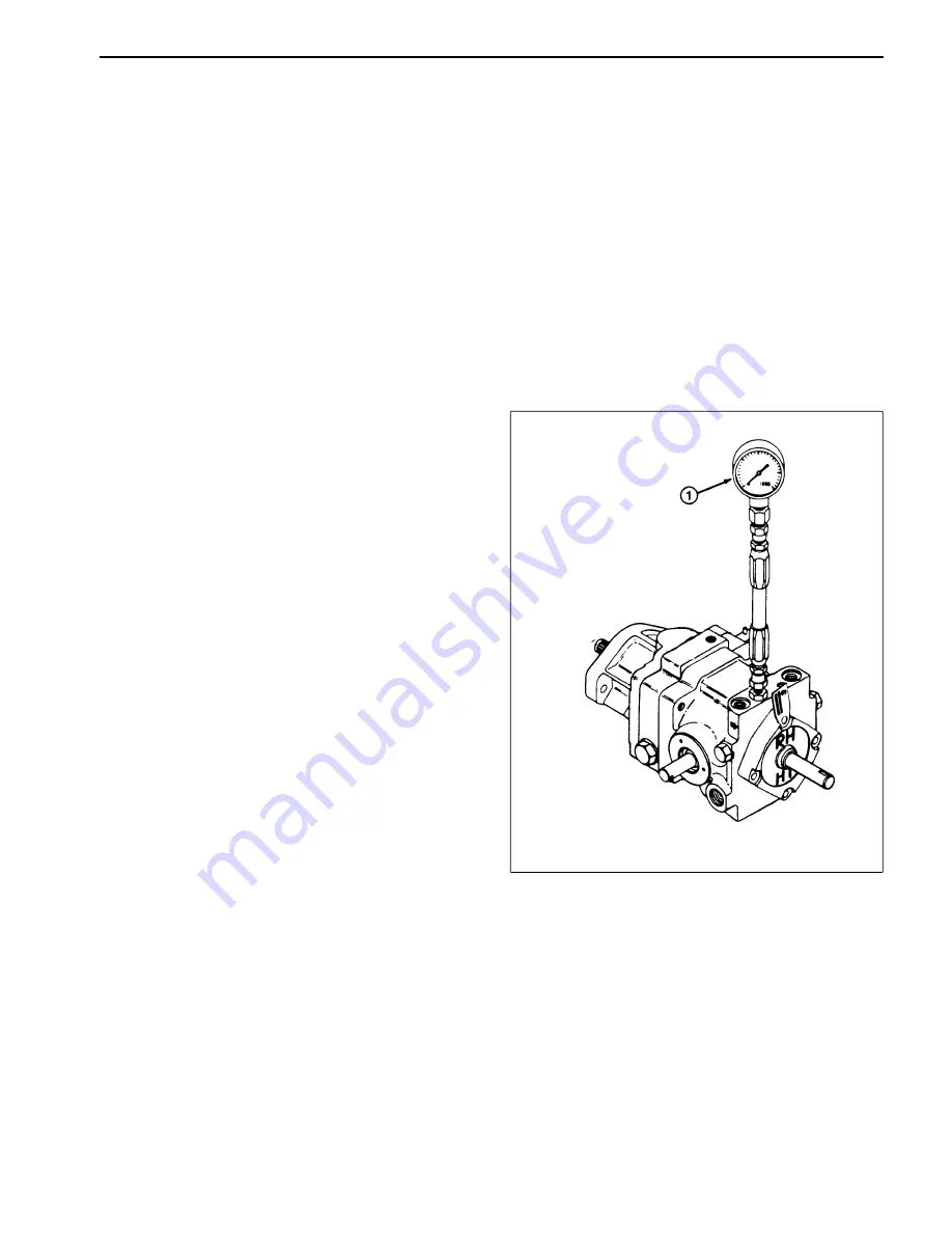
TEST NO. 1: Charge Pressure (Fig. 9)
Using a low pressure gauge: 0 - 1000 psi
1. Engage the parking brake, and block the front wheels
to prevent movement of the machine. Lower the cutting
unit or implement to the floor and turn the engine OFF.
2. Raise and support the seat.
3. Place a drain pan under the transmission. Use a 3/16
inch Allen wrench to remove the 1/8 inch pipe plug
located next the implement pressure port on top of the
transmission.
4. Connect the 0 - 1000 psi hydraulic gauge hose into
the 1/8 inch pipe opening.
5. Start the engine and move the throttle to SLOW so
that the engine idles. Use a tachometer to verify that the
engine is running at 1500
±
50 rpm. The engine must
idle at this speed to provide sufficent charge pump flow
and pressure to lubricate the internal parts of the trans-
mission.
6. Allow the engine to run for approximately 5 minutes
so that the hydraulic oil reaches normal operating
temperature.
7. Increase the engine speed to the FULL throttle setting
and use a tachometer to verify that the engine is running
at 3200
±
50 rpm.
8. Observe the pressure measurement on the low pres-
sure gauge. The reading should be 70 - 150 psi.
NOTE: A higher reading may be obtained due to the
back pressure in the system. This is acceptable.
9. If the pressure is below 70 psi, adjust the charge relief
valve by adding the required amount of shims from the
shim pack.
NOTE: If adding shims to the relief valve does not
increase the pressure, inspect the condition of the
charge pump gerotor and internal housing.
If the charge pump is in good condition (no scoring,
scratches, or excessive wear), the general condition of
the transmission’s piston pump and piston motor might
be suspected of wear and inefficiency.
A lack of minimum charge pressure or low flow could be
due to the fact that the charge pump is having to direct
all of its flow to the main traction circuit (piston pump
and piston motor). When this occurs, oil pressure may
not increase to the 70 - 150 psi pressure necessary to
open the charge relief valve; therefore, no oil can flow
into the steering and implement circuit.
Figure 9
1. Low pressure gauge (0 - 1000 psi)
Groundsmaster
®
300 Series
Page 5 - 19
Testing
Summary of Contents for Groundsmaster 328-D
Page 2: ......
Page 12: ...Torque Specifications Page 2 4 Rev A Groundsmaster 300 Series ...
Page 44: ...Troubleshooting Page 4 16 Groundsmaster 300 Series ...
Page 45: ...Groundsmaster 300 Series Page 4 17 Troubleshooting ...
Page 171: ...Groundsmaster 300 Series Page 6 25 Testing ...
Page 220: ...Repairs Page 7 24 Groundsmaster 300 Series ...
Page 320: ...Troubleshooting Troubleshooting Page 11 4 Groundsmaster 300 Series ...
Page 348: ...Troubleshooting Troubleshooting Page 12 4 Groundsmaster 300 Series ...
Page 379: ...Troubleshooting Groundsmaster 300 Series Page 13 3 Troubleshooting ...
Page 400: ...This page is blank ...
Page 401: ...This page is blank ...


