Hydraulic
System
Reelmaster 5500-D
Hydraulic System (Rev. C)
Page 4 - 15
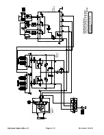
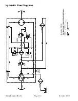
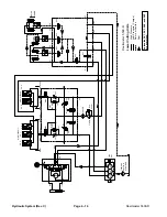
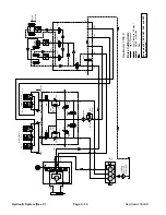
Lower Cutting Units
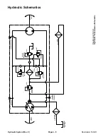
A three section, gear pump is driven off the PTO output
shaft of the hydrostatic transmission. Pump section (P3)
provides oil flow through the steering control valve and
lift manifold to all five cutting unit lift cylinders. Maximum
circuit pressure (1450 PSI) is limited by a relief valve in
the gear pump.
When the cutting units are in the raised position, flow
from the gear pump (P3) passes through the steering
control valve and into the lift manifold. All lift manifold so-
lenoid valves are de-energized and flow is directed to
the hydraulic reservoir.
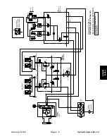
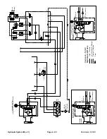
To lower the cutting units, solenoid valves (SV3), (SV4),
and (SV5) energize along with solenoid valve (SV1). So-
lenoid valve (SV2) is in its normally de-energized posi-
tion, and directs oil flow to the piston end of the lift
cylinders. Hydraulic pressure against the piston side of
the cylinder causes the shafts to extend, and lower the
cutting units. When the solenoids are deenergized, the
lift cylinders are held in the lowered position.
Pressure to the lift manifold can be monitored at port
(G3).
The lowering speed of the cutting units are regulated by
3 flow control valves. Flow control valves (2) that regu-
late lift cylinders #1, 4, and 5 are located on the main lift
manifold below the operator’s platform. The remaining
flow control valve that regulates lift cylinders #2 & 3 is lo-
cated in the rear of the traction unit.
Summary of Contents for 00075SL
Page 2: ...Reelmaster 5500 D ...
Page 4: ...Reelmaster 5500 D ...
Page 6: ...Reelmaster 5500 D ...
Page 64: ...Reelmaster 5500 D Hydraulic System Rev C Page 4 26 This page is intentionally blank ...
Page 170: ...Reelmaster 5500 D Page 5 40 Electrical System Rev C ...
Page 192: ...Reelmaster 5500 D Differential Axle Page 6 22 ...
Page 254: ...Reelmaster 5500 D Groomer Rev C Page 8 1 14 ...
Page 278: ...Reelmaster 5500 D Page 10 2 Electrical Diagrams Rev C ...
Page 284: ...Rev C Page 10 8 Harness Drawing Reelmaster 5500 D Serial Number 210000401 to 210999999 ...
Page 285: ...Rev C Page 10 9 Harness Diagram Reelmaster 5500 D Serial Number 210000401 to 210999999 ...
Page 286: ...Rev C Page 10 10 Harness Drawing Reelmaster 5500 D Serial Number 220000001 to 220999999 ...
Page 287: ...Rev C Page 10 11 Harness Diagram Reelmaster 5500 D Serial Number 220000001 to 220999999 ...
Page 288: ...Rev C Page 10 12 Harness Drawing Reelmaster 5500 D Serial Number Above 230000000 ...
Page 289: ...Rev C Page 10 13 Harness Diagram Reelmaster 5500 D Serial Number Above 230000000 ...
Page 290: ...Reelmaster 5500 D ...

