Reelmaster 5500-D
Page 5 - 34
Electrical System (Rev. C)
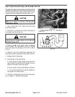
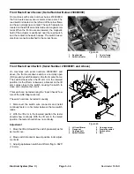
Front Reels Down Sensor (Serial Number Below 230000000)
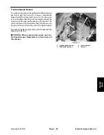
On machines with serial numbers below 230000000,
the front reels down sensor consists of two parts. The
reed switch is located on the left end of the carrier frame
and has a normally open contact. The switch actuator is
located on the left lift arm and is made of a magnetic ma-
terial. When the front reels are lowered, the magnetic
field of the actuator is positioned near the reed switch,
and the contact in the switch closes. The switch has an
electrical connector attached to the carrier frame.
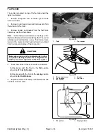
1. Reed
switch
2. Switch
actuator
3. Carrier
frame
4. Lift arm (LH)
Figure 48
1
2
3
4
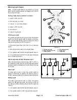
Front Reels Down Switch (Serial Number 230000001 and Above)
On machines with serial numbers 230000001 and
above, the front reels down switch is a normally open
(NO) proximity switch located on the front carrier frame.
The switch closes when the lift arm is in the lowered
position. As the lift arm is lowered, a bracket on the lift
arm comes close to the switch, causing the switch to
close and complete the circuit.
This switch can be tested using the “Input Checks” fea-
ture of the ACE Diagnostic tool.
The switch can also be tested manually.
1. Disconnect the switch wire connector and install
continuity tester or ohm meter between the two switch
leads.
2. With the lift arm in the lowered position the tester
should show continuity. With the lift arm in the raised
position, the tester should show no continuity.
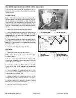
Adjustment
1. Move the lift arm toward the switch (rearward) as far
as it will move.
2. Move switch bracket to lowest position in its adjust-
ment slot.
3. Adjust gap between switch and lift arm flag to .0625”
(1.6 mm).
1. LH front lift arm
2. Flange
nut
3. Carriage
bolt
4. Switch
bracket
5. Carriage
screw
6. Proximity
switch
7. Switch
plate
8. Nut
Figure 49
6
7
2
1
4
3
5
8
Summary of Contents for 00075SL
Page 2: ...Reelmaster 5500 D ...
Page 4: ...Reelmaster 5500 D ...
Page 6: ...Reelmaster 5500 D ...
Page 64: ...Reelmaster 5500 D Hydraulic System Rev C Page 4 26 This page is intentionally blank ...
Page 170: ...Reelmaster 5500 D Page 5 40 Electrical System Rev C ...
Page 192: ...Reelmaster 5500 D Differential Axle Page 6 22 ...
Page 254: ...Reelmaster 5500 D Groomer Rev C Page 8 1 14 ...
Page 278: ...Reelmaster 5500 D Page 10 2 Electrical Diagrams Rev C ...
Page 284: ...Rev C Page 10 8 Harness Drawing Reelmaster 5500 D Serial Number 210000401 to 210999999 ...
Page 285: ...Rev C Page 10 9 Harness Diagram Reelmaster 5500 D Serial Number 210000401 to 210999999 ...
Page 286: ...Rev C Page 10 10 Harness Drawing Reelmaster 5500 D Serial Number 220000001 to 220999999 ...
Page 287: ...Rev C Page 10 11 Harness Diagram Reelmaster 5500 D Serial Number 220000001 to 220999999 ...
Page 288: ...Rev C Page 10 12 Harness Drawing Reelmaster 5500 D Serial Number Above 230000000 ...
Page 289: ...Rev C Page 10 13 Harness Diagram Reelmaster 5500 D Serial Number Above 230000000 ...
Page 290: ...Reelmaster 5500 D ...

