Cutting Units
Reelmaster 5500-D
Page 8 - 27
Cutting Units
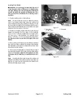
Cutting Unit Installation
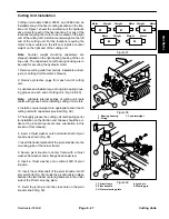
Cutting unit models 03860, 03861, and 03862 can be
installed at any of the five mounting locations on the trac-
tion unit. Figure 1 shows the orientation of the hydraulic
drive motor for each of the five locations. For any of the
locations requiring the motor to be mounted on the right
end of the cutting unit, install a counter weight on the left
end of the cutting unit. For the locations requiring the
motor to be mounted on the left end, install a counter
weight on the right end of the cutting unit.
Note:
Counter weight mounting capscrews are
shipped installed on the right bearing housing of the cut-
ting units. The capscrews on left bearing housing are to
be used for securing the hydraulic motor.
1. Remove cutting units from cartons. Assemble and ad-
just per Cutting Unit Operator’s Manual.
2. Remove protective plugs from each end of cutting
unit.
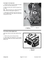
3. Lubricate and install a large O-ring into bearing hous-
ing groove on each end of cutting unit (Fig. 38 & 40).
Note:
Lubricate internal splines of cutting unit reels
shafts with grease before installing cutting unit motors.
4. Install a counter weight onto appropriate end of each
cutting unit with capscrews provided (Fig. 38).
5. Thoroughly grease the cutting unit reel bearings prior
to installation on the traction unit. Grease should be evi-
dent at the inboard reel seals (see Lubrication in this
section of this manual).
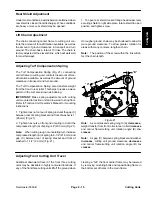
6. Insert a thrust washer onto horizontal shaft of pivot
knuckle as shown (Fig. 39).
7. Insert the horizontal shaft of the pivot knuckle into the
mounting tube of the carrier frame.
8. Secure pivot knuckle to carrier frame with a thrust
washer, flat washer and a flange head capscrew.
9. Insert a thrust washer onto vertical shaft of pivot
knuckle.
10. Insert the vertical shaft of the pivot knuckle into lift
arm pivot hub (Fig. 39). Guide the pivot knuckle in place
between the two rubber centering bumpers in the under
side of the lift arm steering plate.
11. Insert the lynch pin into the cross hole on the pivot
knuckle shaft (Fig. 39).
Figure 37
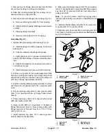
Motor
Weight
Motor
Weight
Weight
Motor
Weight
Motor
Weight
Motor
#1
#4
#5
#3
#2
Figure 38
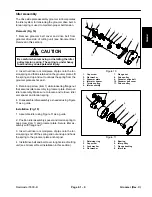
1. Bearing housing
2. O-ring
3. Counterweight
3
2
1
Figure 39
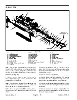
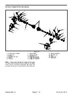
1. Carrier frame
2. Pivot knuckle
3. Lift arm steering plate
1
2
3
4. Lynch pin
5. Steering pin
5
4
Summary of Contents for 00075SL
Page 2: ...Reelmaster 5500 D ...
Page 4: ...Reelmaster 5500 D ...
Page 6: ...Reelmaster 5500 D ...
Page 64: ...Reelmaster 5500 D Hydraulic System Rev C Page 4 26 This page is intentionally blank ...
Page 170: ...Reelmaster 5500 D Page 5 40 Electrical System Rev C ...
Page 192: ...Reelmaster 5500 D Differential Axle Page 6 22 ...
Page 254: ...Reelmaster 5500 D Groomer Rev C Page 8 1 14 ...
Page 278: ...Reelmaster 5500 D Page 10 2 Electrical Diagrams Rev C ...
Page 284: ...Rev C Page 10 8 Harness Drawing Reelmaster 5500 D Serial Number 210000401 to 210999999 ...
Page 285: ...Rev C Page 10 9 Harness Diagram Reelmaster 5500 D Serial Number 210000401 to 210999999 ...
Page 286: ...Rev C Page 10 10 Harness Drawing Reelmaster 5500 D Serial Number 220000001 to 220999999 ...
Page 287: ...Rev C Page 10 11 Harness Diagram Reelmaster 5500 D Serial Number 220000001 to 220999999 ...
Page 288: ...Rev C Page 10 12 Harness Drawing Reelmaster 5500 D Serial Number Above 230000000 ...
Page 289: ...Rev C Page 10 13 Harness Diagram Reelmaster 5500 D Serial Number Above 230000000 ...
Page 290: ...Reelmaster 5500 D ...

