Cutting Units
Reelmaster 5500-D
Page 8 - 9
Cutting Units
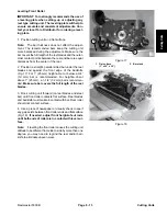
C. Recheck reel to bedknife contact on both ends of
the bedknife. If necessary, repeat step B.
Note:
Reel to bedknife contact may become too tight
or too loose after previous adjustment; therefore, turn
bedknife adjustment knob, accordingly, for light contact.
D. Retighten pivot hub lock nuts.
Note:
Recheck if paper cuts on both ends, to insure
the bedknife did not move when re−tightening the pivot
hub lock nuts.
Adjusting and Leveling Rollers
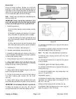
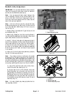
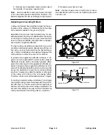
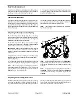
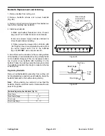
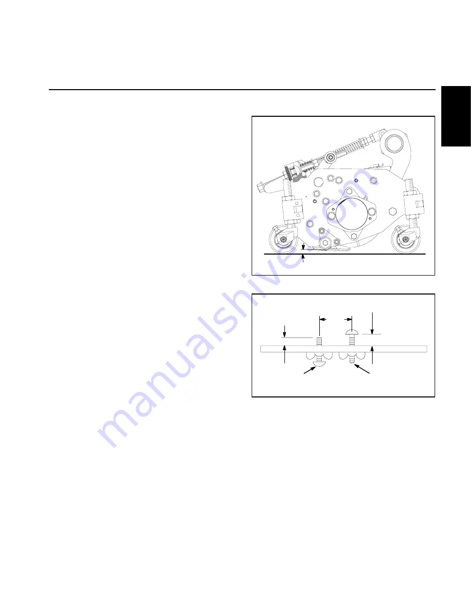
Cutting unit “attitude” has a significant impact on the per-
formance of the cutting unit. Attitude refers to the angle
of the bedknife relative to the ground (Fig.12).
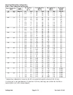
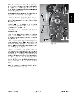
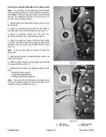
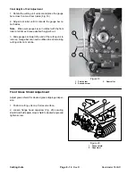
Adjustable front and rear roller brackets allow for vari-
able adjustment of cutting unit attitude within the height-
of-cut range. All cutting units on a given machine must
be set to the same attitude, otherwise after-cut appear-
ance could be negatively affected.
The best cutting unit attitude is dependent on your turf
conditions and desired results. Experience with the cut-
ting unit on your turf will determine the best setting to
use. Cutting unit attitude can be adjusted throughout the
cutting season to allow for various turf conditions.
In general, less aggressive attitudes (example: 2 de-
grees) are more appropriate for warm season grasses
(Bermuda, Zoysia) while cool season grasses (Blue-
grass, Rye) may require more aggressive attitudes (ex-
ample: 6 degrees). More aggressive attitudes cut more
grass off by allowing the spinning reel to pull more grass
up into the bedknife. An angle that is too flat (attitude
less than 1 degree) may allow the bedbar or other parts
of the cutting unit to drag in the turf causing tufting.
Therefore, minimum recommended attitude is 1 degree.
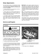
For setting consistent cutting unit attitude, Toro strongly
recommends using a two-screw gauge bar, Toro part no.
98-1852 (Fig.13). The first screw is set for height-of-cut,
and the second screw is set for cutting unit attitude. The
second screw setting is an easy method of transferring
cutting unit attitude to all cutting units on a machine.
Figure 12
ATTITUDE
“A”
2.00”
(51 mm)
Figure 13
HOC SETTING
ATTITUDE
First Screw
Second Screw
Summary of Contents for 00075SL
Page 2: ...Reelmaster 5500 D ...
Page 4: ...Reelmaster 5500 D ...
Page 6: ...Reelmaster 5500 D ...
Page 64: ...Reelmaster 5500 D Hydraulic System Rev C Page 4 26 This page is intentionally blank ...
Page 170: ...Reelmaster 5500 D Page 5 40 Electrical System Rev C ...
Page 192: ...Reelmaster 5500 D Differential Axle Page 6 22 ...
Page 254: ...Reelmaster 5500 D Groomer Rev C Page 8 1 14 ...
Page 278: ...Reelmaster 5500 D Page 10 2 Electrical Diagrams Rev C ...
Page 284: ...Rev C Page 10 8 Harness Drawing Reelmaster 5500 D Serial Number 210000401 to 210999999 ...
Page 285: ...Rev C Page 10 9 Harness Diagram Reelmaster 5500 D Serial Number 210000401 to 210999999 ...
Page 286: ...Rev C Page 10 10 Harness Drawing Reelmaster 5500 D Serial Number 220000001 to 220999999 ...
Page 287: ...Rev C Page 10 11 Harness Diagram Reelmaster 5500 D Serial Number 220000001 to 220999999 ...
Page 288: ...Rev C Page 10 12 Harness Drawing Reelmaster 5500 D Serial Number Above 230000000 ...
Page 289: ...Rev C Page 10 13 Harness Diagram Reelmaster 5500 D Serial Number Above 230000000 ...
Page 290: ...Reelmaster 5500 D ...

