Reelmaster 5500-D
Steering and Brakes
Page 7 - 14
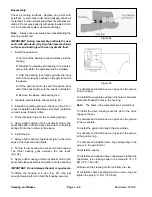
Steering Cylinder
Removal
1. Engage the parking brakes, lower the cutting units to
the ground, turn the engine OFF and remove the key
from the ignition switch.
2. Disconnect the hydraulic hoses from the steering
cylinder. Put caps or plugs on all the fittings and hoses
to prevent contamination.
Note:
To ease reassembly, tag each of the hoses to
show their correct position on the steering cylinder.
3. Remove the steering cylinder as follows:
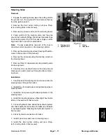
A. (2WD) Remove the lock nut and cap screw secur-
ing the rod end of the cylinder to the steering pivot
(Fig. 16).
B. Remove the lock nut and cap screw securing the
barrel end of the cylinder to the rear axle. Remove
the steering cylinder.
A. (4WD) Remove the retaining ring securing the
rod end of the cylinder to the bevel gear case
(Fig. 17).
B. Remove the retaining ring securing the barrel end
of the cylinder to the cylinder mounting bracket. Re-
move the steering cylinder.
Installation
1. Install the steering cylinder as follows:
A. (2WD) Hold the steering cylinder in position and
install the lock nut and cap screw securing the barrel
end of the cylinder to the rear axle (Fig. 16).
B. Install the lock nut and cap screw securing the rod
end of the cylinder to the steering pivot.
C. Tighten the cylinder mounting cap screws and
nuts to 130 to150 ft-lbs. (176 to 203 Nm).
A. (4WD) Hold the steering cylinder in position and
install the retaining ring securing the barrel end of the
cylinder to the cylinder mounting bracket (Fig. 17).
B. Install the retaining ring securing the rod end of
the cylinder to the bevel gear case.
2. Connect hydraulic hoses. Bleed the hydraulic sys-
tem and check hydraulic connections for leaks (see
Chapter 4−Hydraulic System “Bleeding the Hydraulic
System” in this manual).
1. Steering cylinder
2. Locknut and capscrew
Figure 16
1
2
2
1
1. Steering
cylinder
2. Retaining
ring
Figure 17
2
Summary of Contents for 00075SL
Page 2: ...Reelmaster 5500 D ...
Page 4: ...Reelmaster 5500 D ...
Page 6: ...Reelmaster 5500 D ...
Page 64: ...Reelmaster 5500 D Hydraulic System Rev C Page 4 26 This page is intentionally blank ...
Page 170: ...Reelmaster 5500 D Page 5 40 Electrical System Rev C ...
Page 192: ...Reelmaster 5500 D Differential Axle Page 6 22 ...
Page 254: ...Reelmaster 5500 D Groomer Rev C Page 8 1 14 ...
Page 278: ...Reelmaster 5500 D Page 10 2 Electrical Diagrams Rev C ...
Page 284: ...Rev C Page 10 8 Harness Drawing Reelmaster 5500 D Serial Number 210000401 to 210999999 ...
Page 285: ...Rev C Page 10 9 Harness Diagram Reelmaster 5500 D Serial Number 210000401 to 210999999 ...
Page 286: ...Rev C Page 10 10 Harness Drawing Reelmaster 5500 D Serial Number 220000001 to 220999999 ...
Page 287: ...Rev C Page 10 11 Harness Diagram Reelmaster 5500 D Serial Number 220000001 to 220999999 ...
Page 288: ...Rev C Page 10 12 Harness Drawing Reelmaster 5500 D Serial Number Above 230000000 ...
Page 289: ...Rev C Page 10 13 Harness Diagram Reelmaster 5500 D Serial Number Above 230000000 ...
Page 290: ...Reelmaster 5500 D ...


