Hydraulic
System
Reelmaster 5500-D
Hydraulic System (Rev. C)
Page 4 - 69
Charge Pump Replacement
1. Park machine on a level surface, lower cutting units,
stop engine, engage parking brake, and remove key
from the ignition switch.
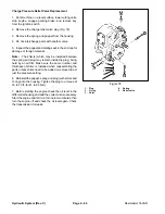
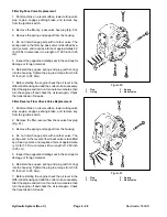
2. Remove the transmission to engine driveshaft
(Fig. 82).
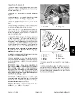
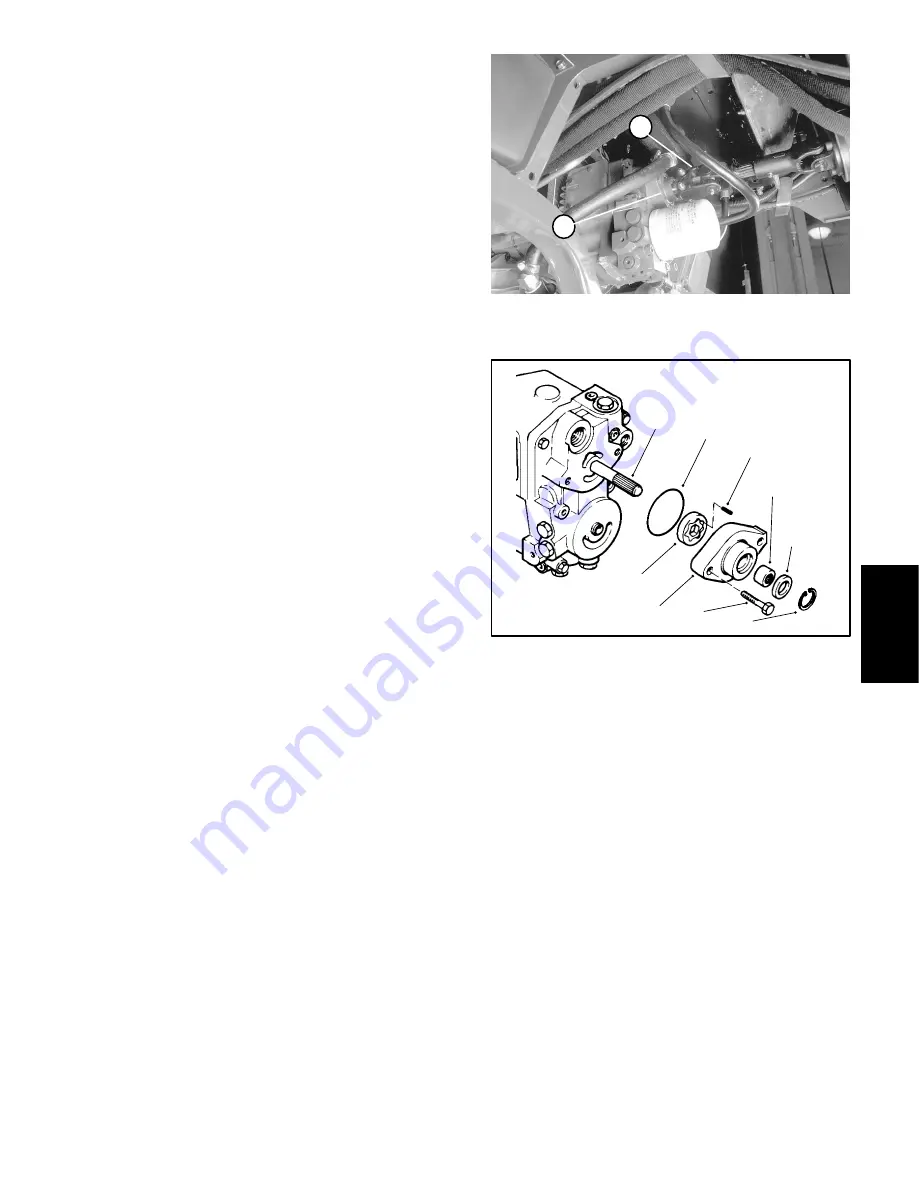
3. Remove the two (2) cap screws retaining the charge
pump cover. Remove the charge pump (Fig. 83).
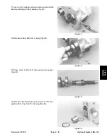
4. Remove geroter drive pin from the groove in the
shaft.
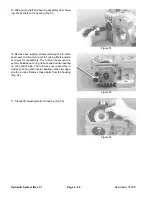
5. Remove the geroter assembly from the charge pump
cover. Remove the shaft seal from the cover.
6. Each part should be inspected separately if they are
to be reused. If either of the geroter assembly parts
needs to be replaced, they should both be replaced. Al-
ways replace the O-ring.
7. Inspect the shaft bearing in the charge pump cover
for wear or damage. If replacement is necessary, re-
move the needle bearing from the cover using a suitable
puller. Press a new needle bearing into the cover using
a suitable press pin. When installed correctly, the bear-
ing cage will be flush to 0.020 inch (.51 mm) below the
surface of the seal counterbore in the front of the cover.
IMPORTANT: When installing the needle bearing,
the printed (numbered) end of the bearing cage
must face the press pin.
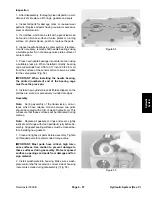
8. Install the geroter drive pin in the groove in the drive
shaft, and retain with petroleum jelly.
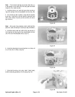
9. Before assembly, lubricate the geroter assembly
with clean hydraulic oil. Install the geroter assembly into
the charge pump cover. Install the O-ring and retain with
petroleum jelly.
IMPORTANT: Correct charge pump installation to
match engine rotation is determined by the position
of the charge pump cover on the transmission
housing. To prevent damage to transmission from
lack of replenishing oil from charge pump, the flat
on the charge pump cover must be on the right (to-
ward the heat exchanger ports).
10.With the flat on the charge pump cover to the right,
install the charge pump assembly over the drive shaft
and onto the transmission housing. Make sure the ger-
oter engages the drive pin in the shaft.
11. Tighten the charge pump cover cap screws to a
torque of 27 to 37 ft.-lb (37 to 50 N-m).
1. Drive
shaft
2. Charge
pump
Figure 82
2
1
8
7
6
4
3
5
9
2
1
1. Retaining
ring
2. Lip
seal
3. Cap
screw
4. Bearing
5. Housing
6. Gerotor
7. O-ring
8. Drive
shaft
9. Needle
bearing
Figure 83
12.Install a new shaft seal (see Shaft Seal Replace-
ment).
13.Before starting the engine, check the oil level in dif-
ferential housing and add the correct oil as necessary.
Start the engine and let it run for one to two minutes, then
turn the engine off and check the oil level again. Check
the transmission for leaks.
Summary of Contents for 00075SL
Page 2: ...Reelmaster 5500 D ...
Page 4: ...Reelmaster 5500 D ...
Page 6: ...Reelmaster 5500 D ...
Page 64: ...Reelmaster 5500 D Hydraulic System Rev C Page 4 26 This page is intentionally blank ...
Page 170: ...Reelmaster 5500 D Page 5 40 Electrical System Rev C ...
Page 192: ...Reelmaster 5500 D Differential Axle Page 6 22 ...
Page 254: ...Reelmaster 5500 D Groomer Rev C Page 8 1 14 ...
Page 278: ...Reelmaster 5500 D Page 10 2 Electrical Diagrams Rev C ...
Page 284: ...Rev C Page 10 8 Harness Drawing Reelmaster 5500 D Serial Number 210000401 to 210999999 ...
Page 285: ...Rev C Page 10 9 Harness Diagram Reelmaster 5500 D Serial Number 210000401 to 210999999 ...
Page 286: ...Rev C Page 10 10 Harness Drawing Reelmaster 5500 D Serial Number 220000001 to 220999999 ...
Page 287: ...Rev C Page 10 11 Harness Diagram Reelmaster 5500 D Serial Number 220000001 to 220999999 ...
Page 288: ...Rev C Page 10 12 Harness Drawing Reelmaster 5500 D Serial Number Above 230000000 ...
Page 289: ...Rev C Page 10 13 Harness Diagram Reelmaster 5500 D Serial Number Above 230000000 ...
Page 290: ...Reelmaster 5500 D ...

